Northwestern Design Competition
Official Website for DC (including the rules of the game)
DC2022

DC2020
Link to google doc instructions
DC2019
- Thursday 5/9/19
- Thursday 5/2/19
- Competition arena:

- Barriers must be placed in the purple squares
- Ships can be placed at any location
- Tuesday 4/16/19
- Get a MAX14870 Pololu motor driver and solder the header pins so that the text side faces up
- Get a 12V 160rpm Pololu N20 motor
- Solder 28 gauge stranded wire to the motor terminals. DO NOT USE SOLID CORE WIRE, THE TABS WILL BREAK OFF
- Try this sample code to run the motor in both directions: dc2019_esp32_pwm.ino
- The motor is connected to M1 and M2
- Both GND pins go to GND
- VIN can go t the ESP32 USB pin (5V). Later this will be 12V from a battery
- PWM goes to 14 in the sample code, but this can be changed to any pin
- DIR does to 32 in the sample code, but this can be changed to any pin
- Tuesday 4/9/19
- Get a ESP32 Feather, breadboard, and USB cable. Run the sample code from 3/14
- Build a simple retroreflective tape sensor:

- Thursday 4/4/19
- Competition rules
- Enter your team here
- Copy the build log from here and share it with Nick
- Thursday 3/14/19
- Example ESP32 code, using the ESP32 Feather: here
- Example python code, using Mu: here
DC2018
- Tuesday 5/8/18
- Tuesday 4/24/18, 6pm in Ford B100
- Driving motors with a 12V battery and h-bridge
- Tuesday 4/17/18, 6pm in Ford B100
- Detecting retroreflective tape with a laser pointer
- Tuesday 4/10/18, 6pm in Ford B100
- Laser cutting and 3d printing
- Friday 4/6/18
- Competition arena:

- The objects are 2" steel cubes and 3.5" diameter 2" tall steel cylinders
- There are 12 of each object
- Thursday 2/15/18
DC2017
- Saturday, 5/7/17

- Thursday, 3/30/17, 6pm in Ford B100
- The hunter robot is about 12" in diameter, 6" high, covered in retroreflective tape
- The microcontroller is the Teensy 3.5
- The motor driver is the Pololu MAX14870 Single Brushed DC Motor Driver Carrier
- The voltage regulator is the Pololu 5V Step-Up/Step-Down S10V4F5
- Use a 100 ohm resistor in series with the laser to prevent dimming and burnouts
- To read the phototransistor, turn off the laser, read the voltage, turn on the laser, read the voltage, and if the voltage has changed a lot, you are looking at a retroreflective object
- Thursday, 2/23/17, 6pm in Ford B100
- Introduction to the competition rules
- Demo of the remote controlled robot
- How to design a DC robot
- Sensors review: laser scanner
- Winter Kickoff Meeting 1/26/2017, 6-7pm, in Tech M152
- Review the Competition Rules
- Teambuilding exercise
- Pizza!
DC2016
- Winter Kickoff Meeting 1/8/2016, 6-8pm, in Tech M152
- Review the Competition Rules
- Teambuilding exercise
- Pizza!
- Milestone 1 Due Thur, 1/21/2016, 6pm in Ford B100
- CAD
- You can use NX, Solidworks (installed on the computers in B100), or sign up for OnShape, a free, browser based CAD program.
- I'll assume you are using OnShape, since there is no installation necessary. Check out their online tutorial videos:
- Definitely watch the first 12 videos on the OnShape Tutorials page
- You may also want to watch OnShape Intro to CAD
- and OnShape Essential Training
- Use a real mouse, with scroll wheel. You can get by using your laptop trackpad, but a mouse makes things so much easier.
- Assignment: Design a mount for an N20 size gear motor (example: Pololu gearmotor mount)
- If you want to follow along, you can watch how I would do it here
- CAD
- Milestone 2 Due Wed, 1/27/2016, 6pm in Ford B100
- 3D printing
- Save your CAD model as a .stl file, and print it on one of the three Monoprice 3D printers in B100 using Simplify3D.
- Use the standard temperature, speed, and dimension settings. The blue tape does not need to be perfect, try to print on a flat spot until all of the tape has been printed on, then replace it.
- Practice loading and unloading the printer. Use the printer menu to turn on "Preheat". When the extruder is hot, push the lever to disengage the drive motor, gently push the filament into the nozzle, then pull it out. To load, feed the new filament in until plastic starts coming out of the nozzle, as if it were a glue gun.
- Assignment: Design and print a 1"x0.75" rectangle 0.5" thick, with a 0.5" diameter hole in the middle. Measure each dimension with calipers and note how much the size differs from your digital model, and email Nick the results.
- 3D printing
- Milestone 3 Due Thur, 2/4/2016, 6pm in Ford B100
- Design for Laser cutting
- Our laser cutters can only make 90 degree cuts. To build something in 3D, you have to design 2D objects that fit together like puzzle pieces, using crenellation or right-angle dovetails. Rather than using glue, embed nuts and slots for screws to assemble the parts.
- Assignment: Design 3 sides of a 2" cube that assemble with right-angle dovetails and 4-40 t-slots. Assemble the design in CAD.
- Design for Laser cutting
- Milestone 4 Due Thur, 2/11/2016, 6pm in Ford B100
- Arduino coding
- Pick up your Arduino Metro Mini or SAMD21 Mini and breadboard, and solder the header pins
- The Metro Mini is a smaller version of the Arduino UNO. There is a lot of code available for the UNO, but it is slow, with limited memory.
- The SAMD21 is similar to the Arduino Zero. It is fast with lots of memory, but the sample code you find online might not always work. Install the drivers and add the board profile to the Arduino IDE.
- Build a potentiometer, pushbutton, and LED circuit
- Pick up your Arduino Metro Mini or SAMD21 Mini and breadboard, and solder the header pins
- Assignment: Write code that, when you push the button, reads the potentiometer, sends the value to the computer, and sets the LED brightness proportional to the potentiometer angle.
- Arduino coding
- Milestone 5: No meeting on 2/10/2016 or 2/11/2016 Due Thur, 2/18/2016, at 6pm in Ford B100
- Continue Arduino coding
- Edit your circuit to have 1 potentiometer, 2 push buttons, and 2 LEDs (on PWM pins)
- Edit your code so that:
- When no buttons are pushed, both LEDs are at 75% brightness
- When one button is pushed, both LEDs are at 25% for 1 second, then one LED is at 0% and the other at 100% for 1 second, then continue
- When the other button is pushed, both LEDs are at 25% for 1 second, then the other LED is at 0% and the first at 100% for 1 second, then continue
- If the potentiometer is ever between 3 and 4 volts, the LEDs blink alternately at 10 Hz
- After 1 minute has passed, the LEDs turn off forever
- Continue Arduino coding
- Meeting 7 Due Thur, 3/3/2016, 6pm in Ford B100
- Motors, motor drivers, batteries
- Pick up a DC motor, hbridge, and battery pack
- Assignment: 3D print or laser cut a mount for the motor. Write code to set the speed of the motor proportional to the potentiometer angle and match the servo angle to the potentiometer angle.
- Motors, motor drivers, batteries
- Notes about equipment:
- The SAMD21 breakout board has a max input voltage of 6V. It will burn up if you use 12V. Use a USB battery to power the board, or wire up your own 3.3V regulator.
- The Metro Mini breakout board has a max input voltage of 16V, so it should be ok to power it off 12V.
- The h-bridge is from Pololu.
- VIN is the motor voltage, between 2 and 16V (use 12V from the battery).
- VCC is the logic voltage (3.3V or 5V). Do not use 12V.
- Wire the PWM pin to VCC, then use a PWM signal on INA to set the motor speed and a DIO pin on INB to set the motor direction.
- Each team gets 2 12V rechargeable lithium ion batteries and a charger. Shorting the battery will draw more than 10A, generating a huge spark and destroying your circuit. Be very careful!
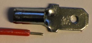
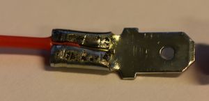
- Use a quick-disconnect terminal to plug into the battery.
- First, pull off the insulation (pull hard!)
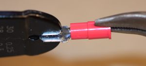
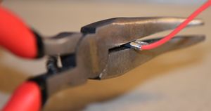
- Next, strip off some wire, so that you can crimp onto the insulation and the wire.
- Then, crimp the back of the connector, on the insulation of the wire.
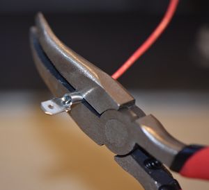
- Then crimp the front of the wire.
- This is what the compete crimp looks like:
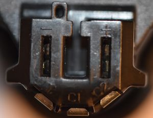
- The top of the battery is labeled with the positive and negative terminals:
- Make a red wire for the positive connection and a black wire for the negative, and test how well they plug in:
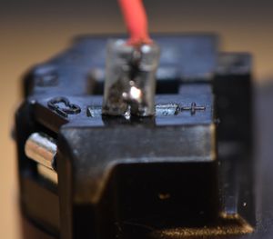
- See if you can 3d print something to hold the red and black wires, so that it can be plugged in only one way (to prevent accidental backwards connections that will destroy your circuit).


DC2015
Winter 2015 Schedule
- Winter Kickoff Workshop 1 - 2/24/15, 6-8pm in Ford B100
- Build a DC2015 Control Board: the blue board!
- Workshop 2 - 3/3/15, 6-8pm in Ford B100
- Build a DC2015 Expansion board: the black board!
- Making things move with the black board
- Building the black board
- Something about attaching to motors
- Build a DC2015 Expansion board: the black board!
- Workshop 3 - 3/10/15, 6-8pm in Ford B100
- Build a DC2015 Protoboard: the green board!
Fall 2014 Schedule
- NU Robotics Workshop 1 - Soldering - 10/22/14 in Ford B100
- Learn how to solder
- DC Kickoff - Around 11/5/14
DC2014
Winter 2014 Schedule
- Kickoff - 1/15/14, 5pm in Tech A110
- Sponsor Talk - MISUMI
- Tue, 1/28/2014, 5pm, Tech M128
- Designing with MISUMI
- Workshop 1 - Robot simulation
- Thur, 1/30/2014, 5pm, Ford B100
- Using a simulator to test robot algorithms
- Milestone 1 - Maze solving robot
- Due by Wed, 2/5/2014
- Show off your robot code solving a maze
- Workshop1 Assignment
- Workshop1 Files
- Workshop 2 - Makerbot and advanced robot simulation
- Thur, 2/6/2014, 5pm, Ford B100
- Using CAD and the Makerbot
- Better dead reckoning in simulation
- Workshop 3 - Makerbot linkages and advanced robot simulation
- Thur, 2/13/2014, 5pm, Ford B100
- Designing 4-bar linkages and printing them on the Makerbot
- Radar and LIDAR in simulation
- Milestone 2 and 3 - Maze solving robot and 3D printed motor mount
- Due by Wed, 3/5/2014
- Design, print and assemble a simple mechanism with the Makerbot
- Use sensors for wall-following
- Workshop2 Assignment
- Workshop2 Files
- Design, print and assemble a 4-bar linkage with the Makerbot
- Use LIDAR for maze solving
- Workshop3 Assignment
- Workshop3 Files
- Competition Format
- 3 competitions: Competition Format
- Milestone 4 Due Monday, 4/14/14, by email to Nick
- Rough mechanical design of your robot. Sketches of legs and drive mechanism, description of mechanism, material list (motors, servo, bearings, etc.)
- Workshop 5 - Roland mill PCBs
- Wed, 4/23/2014, 4pm, Ford B100
- Designing printed circuit boards to be milled on the Roland CNC desktop mill
- Milestone 5 - Robot PCB
- Due by Fri, 4/25/2014
- Design, mill, solder and program a PIC32MX150 PCB for your robot
- Workshop5 Files
- Milestone 6 - Robot PCB
- Instructions on using the PCB mill (beta) :
- Sample code for a simple line following robot using 2 DC drive motors, 3 analog inputs from IR line sensors, output to the Nokia LCD. Also included, sample code for the IR proximity range finder for the NU32, and an .stl for a range finder cap to block light from the LED hitting the sensor.
DC2013
Spring Quarter Schedule
- Workshop 6 - H-Bridges, DC motor control, wheel sensing
- Wed, 4/3/2013, 6pm in mechatronics lab
- workshop6.c - drive a DC motor using PWM with an h-bridge and sense its position with a reflectance sensor
- How to use an h-bridge and a DC motor
- Encoder template
- Milestone 6 - Wheel control
- Meeting in the mechatronics lab at 6pm 4/17
- Demo due by 4/17/2013
- Press the USER button, and the wheel rotates 180 degrees
- Milestone 7 - Complete chassis
- How to design parts that can be 3D printed
- Demo due by 4/24/2013
- Demo your chassis
- Milestone 8 - Driving and sensing the world
- Demo due by 5/1/2013
- Demo your robot driving around the arena and sensing things
- Milestone 9 - Identify prey and drive towards them
- Demo due by 5/8/2013
- Demo your robot chasing Prey
- Milestone 10 - Operational robot, demo for E-Week
- Demo due by 5/15/2013, demo at E-Week in Tech lobby
- Show how your robot works
- COMPETITION!!!!
- 5/18/2013, Noon in the machine shop
Useful things:
- Arena and breakout board

- Write-ups
- Code
- NU32
- Download: MPLAB X IDE and MPLAB XC32 Compiler from http://www.microchip.com/pagehandler/en-us/family/mplabx/#downloads
- Download: FTDI Drivers from http://www.ftdichip.com/Drivers/VCP.htm
- Download: NU32_Utility from NU32:_Software_to_Install
- NU32 from 2012
- We have a lot of left over boards from 2012 but you have to use NU32_Utility_v5 from NU32:_Software_to_Install
- and NU32_2012.c, NU32_2012.h instead of NU32.c and NU32.h
Winter 2013 Schedule
- Workshop 1 - Prey robot deconstruction
- Tue, 1/15/2013, 6pm, Ford B100
- Milestone 1 - Prey robot -> Demobot
- Due by Wed, 1/23/2013
- Show off your Demobot, made from a deconstructed Prey robot DONE!
- Workshop 2 - Programming the PIC32
- Begin Wed, 1/23/2013, meeting in the Mechatronics lab at 6pm
- How to program the PIC32 on the NU32
- Sample code - NU32test.hex, SimplePIC.c, NU32bootloaded.ld, talkingPIC.c, NU32.c, NU32.h
- Milestone 2 - Programming the PIC32
- Due by Wed, 1/30/2013
- Code Template: DC2013_Milestone2.c, NU32.c, NU32.h, NU32bootloaded.ld
- Complete the assignment here: DC2013milestone2.pdf DONE!
- Workshop 3 - Programming the PIC32
- Begin Wed, 1/30/2013, meeting in the Mechatronics lab at 6pm
- How to program the PIC32 on the NU32, sensors and actuators, soldering
- Sample code - DC2013_milestone3.c
- Milestone 3 - Programming the PIC32, sensors and actuators
- Due by Wed, 2/6/2013
- Potentiometers, phototransistors, RC servos, ultrasonic distance sensors
- Complete the assignment here: DC2013milestone3.pdf DONE!
- Workshop 4 - Using the laser cutter
- Begin Wed, 2/6/2013
- How to design parts that can be made on the laser cutter
- Milestone 4 - Laser cutter training
- Due By Wed, 2/20/2013
- Get trained on the laser cutter
- Design and build a robot gripper or mechanism DONE!
- Workshop 5 - RC servo and Laser detection
- Begin Wed, 2/13/2013, at 6pm in the mechatronics lab
- How to use a laser to detect retroreflective tape
- How to buffer and analyse data
- Combining the laser and RC servo to make a moving sensor
- workshop5.dxf - parts that mount the laser, sensors and servo for reference
- workshop5.c - sweep the servo when the user button is pressed, save the data to an array
- Milestone 5 - Target hunting
- Due by Wed, 2/20/2013
- Mount the laser on the servo
- Sweep the laser, find the target, and point at it DONE!
Reading week 6/11-5, finals week 6/18-22, break 3/25-29
DC2012
Scale arena:

Equipment
- NU32, USB cable, 6V power supply
- 2 drive motors, 2 motor mounts, 2 wheels
- large and small RC servos
- red and IR lasers
- 12"x24"x0.118" clear acrylic sheets
- AA batteries and packs
PCB


Workshop 1, Wednesday 1/18 5:30-7pm Tech L221, makeup Thursday 1/19 9-11am Mechatronics Lab
- How to program in MPLABX
- How to use the bootloader to put code on the NU32
- Digital output I/O (read a button and flash an LED)
- Analog input
- PWM output
- Sample code: Sample code for Workshop 1
Milestone 1, due by 1/27
- If a pushbutton is pressed, read the value of a potentiometer and change the brightness of an LED to the corresponding value with PWM
Workshop 2, Thursday 2/9 6-7pm Tech L221, makeup Friday 2/10 9-11am Mechatronics Lab
- Optical isolation for motors and RC servos
- Powering a motor with an h-bridge
- Writing to the 16x2 character LCD
- Laser detection of retroreflective tape / Optical line detection
- 2 1/2D design
Milestone 2, Due week of Feb 27
- Optically isolate a motor
- Read a potentiometer and write its voltage to the LCD
- Control the motor velocity based on the potentiometer reading
- Control an RC servo
- Detect a 3/4" wide black line on white paper with a phototransistor and LED
Laser cutting Workshop, Week of Apr 2
- Laser cutting
- 2.5D design
- Making a chassis, mounting motors and sensors
Chassis Milestone, Due Apr 13
- Demonstrate a robot chassis that can drive around the arena, bonus points for following a line, detecting and moving towards the moving goals, and detecting and moving towards a crate
Midterm Milestone, Due Apr 30 / May 1 / May 2
- Demonstrate some strategy - from the starting position, go get a crate and bring to back towards the goal
Pre-competition Milestone, Due May 9
- Demonstrate some advanced strategy - score several points
Competition May 19!
DC2011
Milestone 1
- On a button press, read the value of a potentiometer and change the brightness of an LED accordingly using PWM. Note: Do not use an h-bridge or motor as previously assigned.
- Due before Workshop 2 on Wed, 2/9.
- Sample code from Workshop 1
Milestone 2
- Due before Workshop 3 on Wed, 2/23.
- Goals:
- Use code from NU32v2: Nokia 5110 LCD and NU32v2: Analog Input to read a potentiometer and print the voltage to the Nokia 5110
- Optically isolate a motor and control its velocity based on the potentiometer reading
- Do 1 of the following:
- Mount a phototransistor to a laser and detect a cake OR
- Detect a line of electrical tape on white paper with an optoreflector
- Datasheets
- HBridge_L293D.pdf - H-bridge for driving a DC motor
- Optocoupler_A847.pdf - Optocoupler to optically isolate your H-bridge
- HexInverter_74HC04.pdf - Inverting chip to digitize optocoupler output
- Optoreflector_OPB740.pdf - Optoreflector to detect lines or color
- Optoreflector_QRE1113.pdf - Optoreflector to detect lines or color
- Phototransistor_SFH310.pdf - Phototransistor to detect lines, color, or laser reflections
- Notes
- DC2011_WS2_OpticalIsolation.pdf - How to optically isolate an h-bridge and servo motor using the A847 and 74HC04
- DC2011_WS2_OpticalSensors.pdf - How to use the SFH310 to detect a cake and use the OPB740 or QRE1113 for line following
- DC2011_WS2_Code.zip - Example code for the NU32v2 that will:
- Control a DC motor hooked up to an optically isolated h-bridge, and control an optically isolated RC servo motor
- Respond to serial commands to control the motors, write to the Nokia 5110, and read two analog signals
Milestone 4
- Due before Wed, 3/16
- Finish laser training, at least one person per team
- Construct a prototype chassis for your robot
- Do one of the following:
- Follow part of the line on the 36" x 96" printout of this pdf
- Detect a cake somewhere on the floor and drive to it
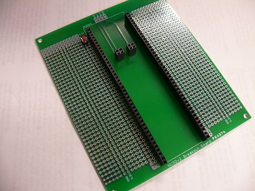
Breakout Boards
- Image of the breakout boards
- Circuit schematic of the breakout boards
- This board contains:
- A spot to plug in the NU32v2 with some prototyping area
- The optical isolation circuit with some prototyping area, the same size as the NU32v2 breakout board so it can be stacked on top
- 8 SFH310 with LED breakout boards
- 4 SFH310 with laser diode breakout boards
- 1 LIS352AX accelerometer breakout board
- 1 LSM303DHL tilt-compensated compass breakout board
- 1 LPY550AL gyroscope breakout board
- 1 LS7366R encoder decoder breakout board
- 1 TCS3103 color sensor breakout board
- How to use the boards:
Solder female header pins to the NU32v2 Breakout Board so that you can plug in and remove your NU32v2 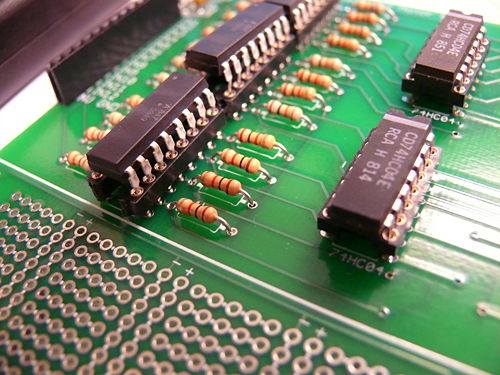
Solder sockets to the Optically Isolated Motor Board so you can remove burnt out chips 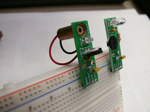
The LED and Laser Phototransistor breakout boards will make it easier to attach wires to the sensors 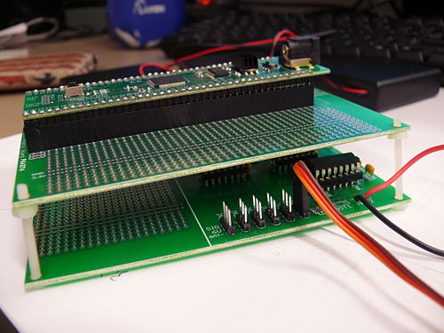
You can stack the NU32v2 breakout board with the Optically Isolated board


Brochure for 2011
Previous Years
Wiki pages on sensors, actuators, programming, and microcontrollers: use pages below
- Parts in the DC2008 quick start pack
- PIC C intro slides, as presented 2008/01/24 (pdf)
- PIC interfacing slides, as presented 2008/01/28 (pdf)
- Link to all sample PIC code here.
Sensors and actuators for DC
- Solderless Breadboard & wiring that works
- Using LEDs & IREDs
- Using a laser
- Infrared reflectivity
- Using phototransistors
- Sensing optical tape
- Comparators : the analog digital interface
- Faulhaber MiniMotor SA gearmotor with encoder, as well as the local wiki page
- Adding a magnetic encoder to a GM3 Gearmotor
- Using magnetic switches (Hall Effect)
- Driving high-current devices: several options
- Driving a Stepper Motor
- Driving an RC Servo
- Accelerometers
- Strain gauges
- Basic Stamp Microcontroller Not recommended for DC2008
- NiMH rechargable batteries and chargers
Prof. Peshkin's favorite datasheets