Uploads by Matt Turpin
From Mech
Jump to navigationJump to search
This special page shows all uploaded files.
| Date | Name | Thumbnail | Size | Description | Versions |
|---|---|---|---|---|---|
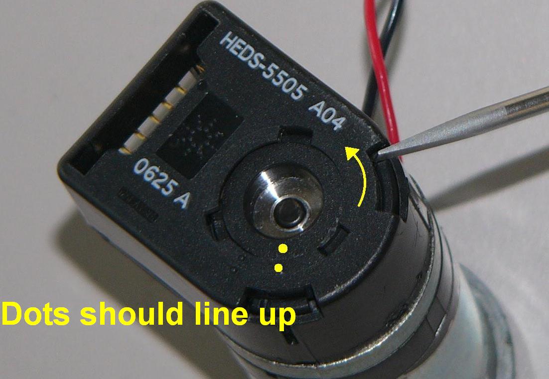
| 16:30, 8 July 2008 | Globe-scredriver-inserted.jpg (file) |  |
88 KB | Insert a small screwdriver into the slot as shown and rotate until the dots line up. | 2 |
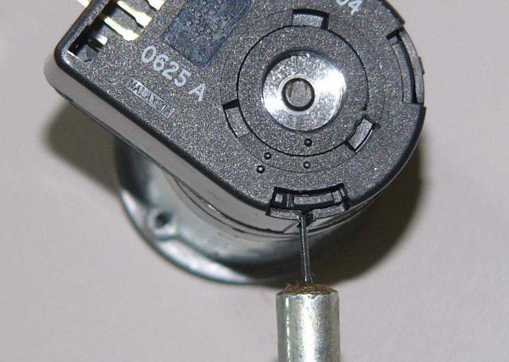
| 16:18, 8 July 2008 | Globe-hex-wrench-inserted.jpg (file) |  |
105 KB | Insert the 0.035 inch hex wrench into the newly exposed slot and turn the pinion until the wrench is inserted into a set screw holding on the encoder wheel. | 3 |
| 16:05, 8 July 2008 | Globe-machined-motor-head.jpg (file) |  |
99 KB | A machined motor head. This can be achieved through milling or interrupted turning of the top part of the motor. | 1 |
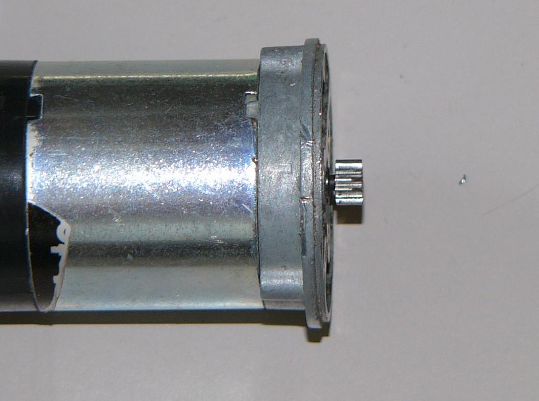
| 16:03, 8 July 2008 | Globe-exposed-pinion.jpg (file) |  |
77 KB | Example of a final exposed pinion. | 1 |
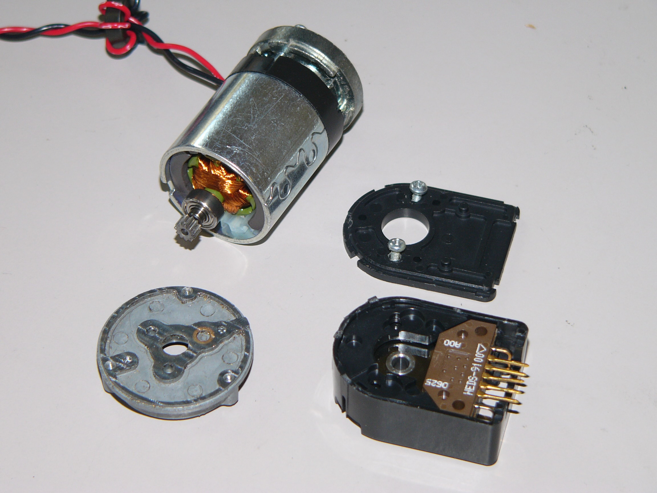
| 16:00, 8 July 2008 | Globe-dissassembled.jpg (file) |  |
454 KB | Disassembled Globe motor. | 1 |
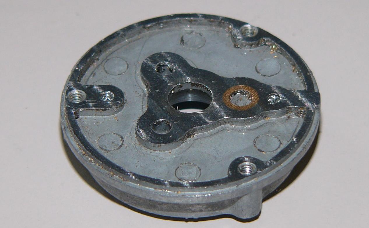
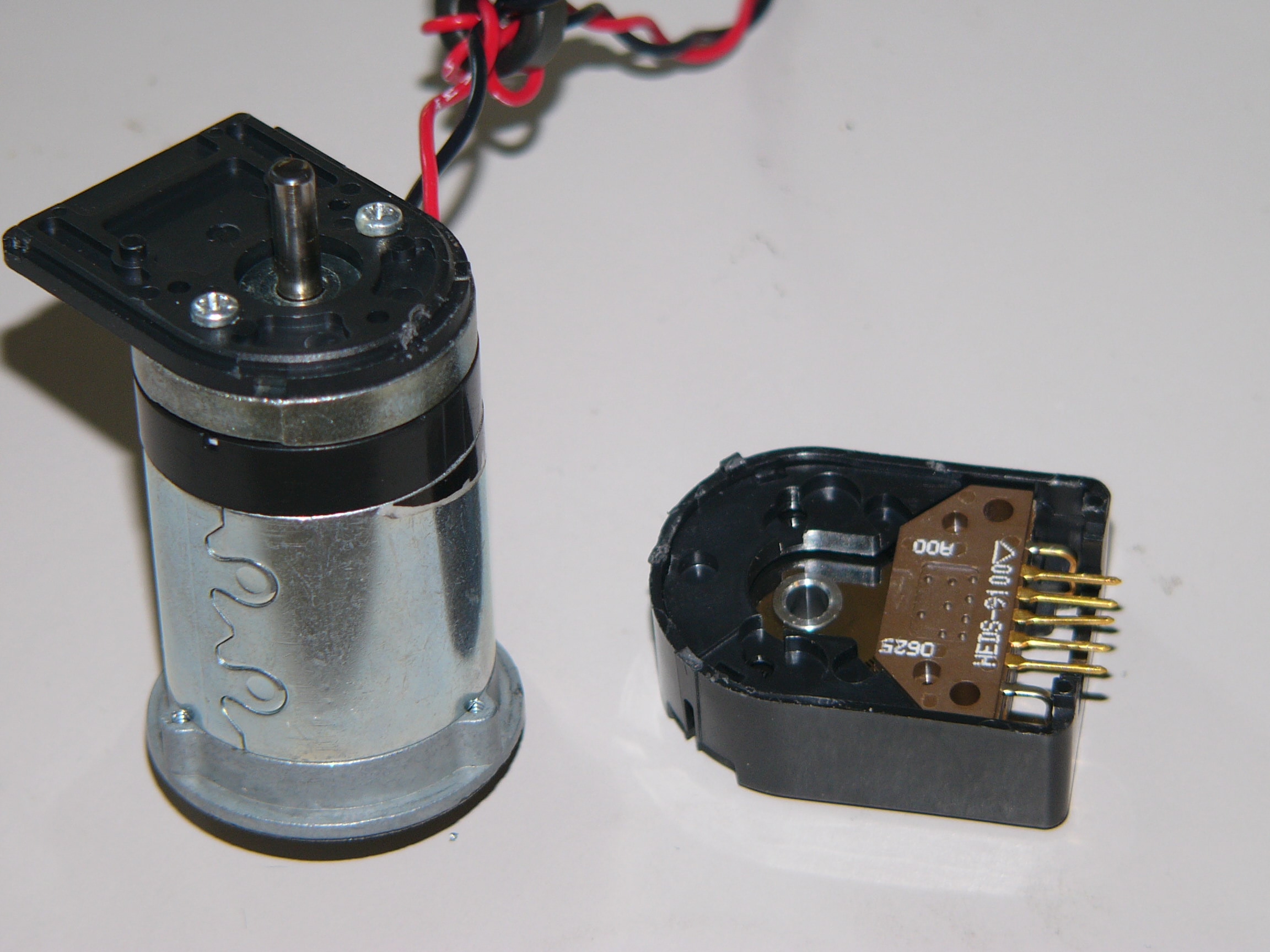
| 15:59, 8 July 2008 | Globe-encoder-removed.jpg (file) |  |
432 KB | Image of the Globe motor with the encoder removed. | 1 |
| 22:02, 16 March 2008 | I2CMotorControllerCode.zip (file) | 10 KB | The PIC C and MATLAB code for the I2C motor controller | 1 | |
| 21:57, 16 March 2008 | I2CMotorController.PDF (file) | 482 KB | A simple easy to construct I2C motor controller for the PIC 18F4520. | 1 | |
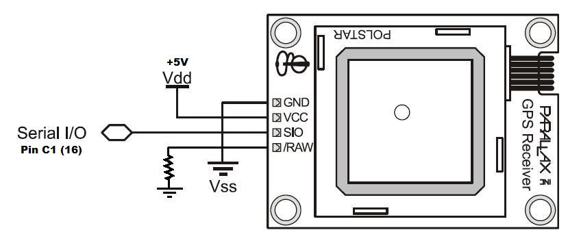
| 01:29, 18 February 2008 | Parallax GPS Wiring Digram.jpg (file) |  |
33 KB | 4 pin connections for the Parallax GPS chip. Note that the pin labeled "Raw" needs to pulled high with a 10k resistor. | 3 |
| 00:56, 18 February 2008 | I2C Alternate Master.c (file) | 2 KB | A master I2C code to demonstrate two way communication. | 4 | |
| 23:02, 6 February 2008 | GPS Raw Data Stream (file) | 25 KB | Here is an example of the serial output of a Parallax GPS module. | 1 | |
| 22:54, 6 February 2008 | ParallaxGPS.c (file) | 3 KB | Full Parallax GPS code with parsing of 3 data selections. | 1 | |
| 22:43, 6 February 2008 | GPS Circuit.jpg (file) |  |
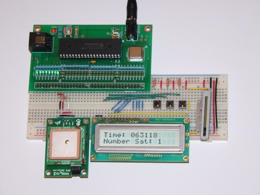
62 KB | An example of how to wire a parallax GPS on one solderless breadboard. | 1 |
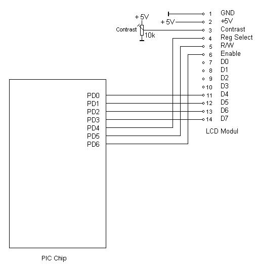
| 22:37, 6 February 2008 | Parallel LCD Wiring Digram.jpg (file) |  |
21 KB | Taken from http://hades.mech.northwestern.edu/wiki/index.php/C_Example:_Parallel_Interfacing_with_LCDs See that page for code and additional information. | 1 |
| 05:02, 3 February 2008 | I2C Alternate Circuit Diagram (file) | 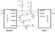 |
62 KB | Switch 3 and analogue inputs are added. | 2 |
| 04:58, 3 February 2008 | I2C Alternate Slave.c (file) | 2 KB | 2 | ||
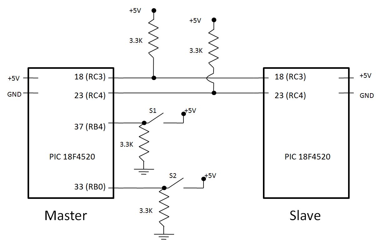
| 21:51, 2 February 2008 | I2C Circuit Diagram.jpg (file) |  |
55 KB | Note that pin 18 is not brought out on the 4520 prototyping board. | 2 |
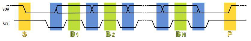
| 21:39, 2 February 2008 | I2C Data Transfer.jpg (file) | 16 KB | A sequence diagram of data transfer on the I²C bus S - Start condition; P - Stop condition; B - One bit transferred; data changes allowed when clock low (blue) | 1 | |
| 21:34, 2 February 2008 | I2C Data Transfer.svg (file) | 12 KB | A sequence diagram of data transfer on the I²C bus S - Start condition; P - Stop condition; B - One bit transferred; data changes allowed when clock low (blue) | 2 | |
| 21:10, 2 February 2008 | I2C Master.c (file) | 1 KB | I2C Master code for reading 2 software de-bounced switches and sending the data byte to the Slave | 1 | |
| 21:08, 2 February 2008 | I2C Slave.c (file) | 793 bytes | I2C Slave code to display 1 byte data transmission | 1 | |
| 19:49, 2 February 2008 | I2C Wiring Image.jpg (file) |  |
125 KB | Note Connecting wires from pin 18 on each PIC. | 1 |