PIC RS232
RS232 serial communication is an ancient, low speed, reliable standard. Each of about 100 characters (a, b, c, 1, 2, 3...) has a one-byte ASCII code. These are transmitted as 8 consecutive low and high logic levels, with a few framing bits as well. Baud rate refers to the number of bits/second. A typical baud rate is 19200, which is about 10000 times slower than USB. The original teletype machines were 110 baud. Read more about RS232 on wikipedia.
All desktop and laptop computers used to have a serial or "COM" port, available through a male DB-9 connector. These are getting less common on newer computers. However you can get an inexpensive "USB to Serial Adapter" cable which makes a COM port available, once you install some driver software to support the adapter cable.
The 18F4520 PIC has a built-in UART for transmitting and receiving characters on RS232 standard. After you make the hardware connection -- the PIC's transmit pin sends to the PC/laptop's receive pin and vice versa -- you can open a text window on the PC/laptop and see whatever your PIC program prints, and type characters that will be transmitted to your PIC. The CCS IDE has a built-in text window for this purpose, shown at the bottom of this page. You can also use Hyperterminal, which actually works somewhat better. It is a Windows ap usually found at Programs/Accessories/Communications/Hyperterminal. You can also set up your PIC to communicate with a Matlab program on a host PC.
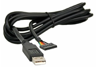
We have two different kinds of cables for PC to PIC RS232 communication: the FTDIChip TTL-232R (preferred) and a cheaper USB to RS232 cable. The TTL-232R is preferred because you can easily plug it into a protoboard and you don't need any other components to interface with your PIC. It also provides +5V output from the PC which you can use to power other devices, such as an xbee radio (just need a 3.3V regulator). The cheaper cable requires you to solder a DB-9 connector and use an external level-shifter chip, to shift between the high voltages used by the PC and the lower TTL voltages used by the PIC. These two solutions are discussed below.
FTDIChip TTL-232R USB to RS232 Cable
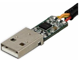
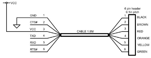
The FTDIChip TTL-232R USB to RS232 cable (pictured at right), when used with the software, allows you to use your USB port as an RS232 port. You can find a manual for the cable here. You connect the cable's TxD (transmit data) pin with your PIC's RxD (receive data, pin 26), the cable's RxD pin with your PIC's TxD (pin 25), and the cable's ground with the PIC's ground, and you're all set. The circuitry inside the cable takes care of the USB to RS232 as well as voltage-level shifting. This cable also provides a 5V output which you can use to power an xbee wireless modem, for example (the xbee needs a 3.3V regulator).
The only drawback of this cable is that it costs a bit more than the cheaper, less convenient option below. Also, please check to make sure that the USB-RS232 driver software does not interfere with your PIC's ICD driver software.
Alternate USB to RS232 Cable
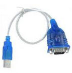
Cables such as the one pictured at right can be bought for as low as a few dollars on ebay, for example. This cable serves the same purpose as the cable above, but it is a bit less convenient for a few reasons: (1) the RS232 voltages are high level (+12V and -7V) and must be level-shifted before interfacing with the PIC; (2) the cable breaks out into a DB-9 connector, so you have to have (or solder) your own connector; and (3) it doesn't provide +5V to power external devices, as the cable above does. Nonetheless, it works just fine; just make sure you follow the instructions below.
Do I need to hook up all 9 pins?
No, you only need three: transmit, receive, and ground. The rest have purposes but are seldom used any more. You do have to get the baud rate and a few other parameters matched, between whatever your two communicating partners are.
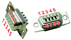
On a standard male DB-9 COM connector on a computer, 2=input to computer, 3=output from computer, 5=ground.
The connector you build will be female with the same pin numbers for the same purposes. Photo at right shows the pin numbering on the female DB-9.
Voltage problems: important!
PC/laptops use +12 volt and -7 volt signals The official RS232 standard uses +12V and -7V for logic 1 and 0 (or maybe the other way around). The PIC can only produce 5V logic levels, and it can be damaged by voltages above 5V. So although the PIC and your PC/laptop agree about the code for transmitting characters, they don't agree about the voltage levels.
Some devices use "5 volt RS232" Quite a lot of devices use 0 and 5V logic levels instead of the higher voltages that the RS232 standard specifies. The PIC does this, and so do Serial 2-line LCD Displays, which are very handy. So these can be connected directly.
Shifting voltage levels
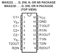
For interfacing a PIC to a PC/laptop or to a Serial-to-USB Adapter, you need a level converter. The MAX232N is a lovely chip that serves this function, in both directions (PC to PIC and PIC to PC). In fact it has two channels in each direction, should you ever want that many. You would think that in order to produce 12V signals it would need a +12V power supply, and maybe a negative supply as well, but it doesn't, it produces the needed +12V and -7V internally from a single convenient 5V supply.
Using the MAX232N
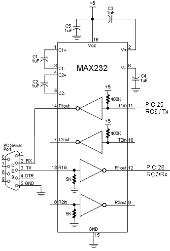
The chip needs five 1uF capacitors around it, which is not a lot to ask for sparing you two extra supply voltages. Connect MAX232N pins 13 & 14 (and ground) to a female DB-9 connector as shown, and plug into your PC/laptop's serial port. Connect MAX232N pins 11 & 12 to your PIC. If you only want PIC output, you don't need to hook up the PIC input.
- PIC to PC: PIN pin 25 (RC6/TX) --> MAX232N pin 11 --> MAX232N pin 14 --> DB-9 pin 2
- PC to PIC: DB-9 pin 3 --> MAX232N pin 13 --> MAX232N pin 12 --> PIC pin 26 (RC7/RX)
Code on the PIC
The essential line is #use rs232(baud=19200, UART1). This sets up the PIC's hardware UART. The PIC can also can do software RS232, but that is susceptible to mistiming caused by interrupts.
Once the UART is set up, you can use most of the usual C serial i/o functions, such as printf(). There's no scanf() in PIC C, and be sure to read about the formatting codes (%d and so on.)
Note - Characters transmitted to the PIC faster than your program reads them cause the UART to choke. After that happens, kbhit() never returns TRUE again, and no characters can be read. So use PIC RS232 input with care. If you want reliable input you have to set up an interrupt on incoming characters.
#include <18f4520.h>
#fuses HS,NOLVP,NOWDT,NOPROTECT
#use delay(clock=20000000)         // 20 MHz crystal on PCB
#use rs232(baud=19200, UART1)      // hardware UART; uses  RC6/TX and RC7/RX

int16 i;
int j;

void main() {

   while (TRUE) {

      for (i=1; i<10000; i++) {
         printf("Hello world. %Lu %u\r\n", i, j);  // \r is carriage return, \n is scroll up
         delay_ms(100);
         if (kbhit()) j = getc();     // type slowly so kbhit() doesn't choke
      }
   }
}
Configuring your COM port and the Loopback Test
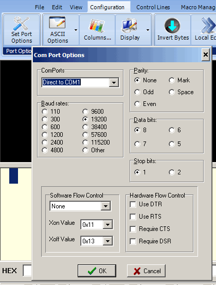
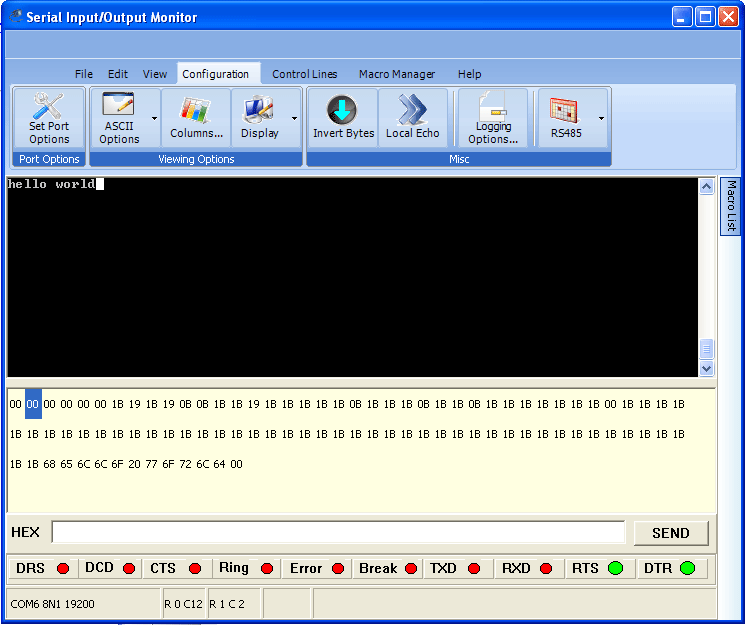
Shown at right are the usual configuration options for the COM port on your computer. Baud rate must match that of the PIC. There is the problem of which COM port to select, and whether the one you have made electrical connection to (through a DB-9 connector) is that one.
To check your COM port, try the Loopback Test. With the DB-9 disconnected, if you type "hello" into the text window ("serial port monitor") you will not see "hello" appear in the window, because your characters went out on pin 3 of the DB-9. The window shows only characters arriving on pin 2 of the DB-9; there is no Local Echo. If you connect pin 2 to pin 3 temporarily and type again, you will now see your words. Thus you have identified electrical signals that correspond to your COM port and text window.
Typical other problems are:
- Different baud rates (sometimes resulting is garbled transmission, sometimes no transmission)
- DB-9 pins 2 & 3 (computer receive and transmit) not going to partner's transmit & receive, respectively
- You didn't level shift appropriately and now things are burned out.
- Partner (e.g. PIC) is not transmitting anything. Look with a scope and see if there's anything happening on partner's transmit line.
