Difference between revisions of "PIC32MX: FFT of Analog Input"
RyanDeeter (talk | contribs) m (→Example Plots) |
|||
| Line 510: | Line 510: | ||
==Example Plots== |
==Example Plots== |
||
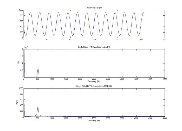
Here is an example using a 500 Hz sine wave input. |
Here is an example using a 500 Hz sine wave input. |
||
[[Image: FFT_500_sin.jpg]] |
[[Image: FFT_500_sin.jpg|border|700px]] |
||
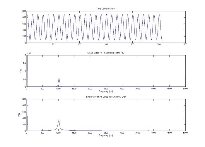
This example uses a 1 kHz sine wave. |
This example uses a 1 kHz sine wave. |
||
[[Image: FFT_1K_sin.jpg]] |
[[Image: FFT_1K_sin.jpg|border|700px]] |
||
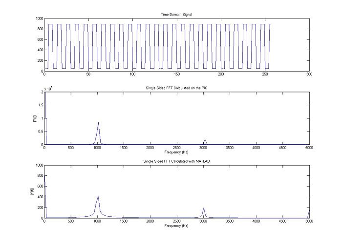
This example is still at 1 kHz, but with a square wave. |
This example is still at 1 kHz, but with a square wave. |
||
[[Image: FFT_1K_square.jpg]] |
[[Image: FFT_1K_square.jpg|border|700px]] |
||
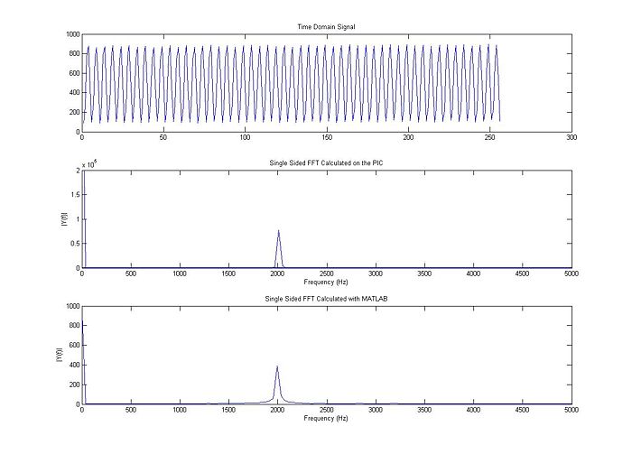
This example shows a 2 kHz sine wave. |
This example shows a 2 kHz sine wave. |
||
[[Image: FFT_2K_sin.jpg]] |
[[Image: FFT_2K_sin.jpg|border|700px]] |
||
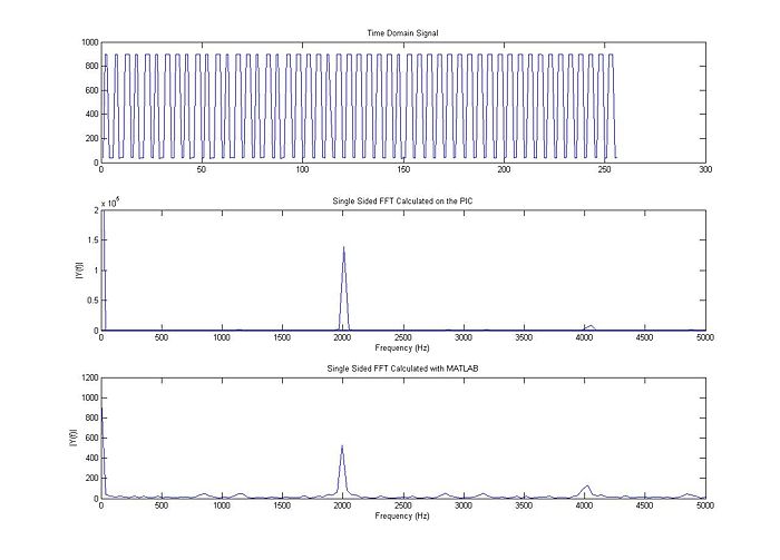
This example, still at 2 kHz, is a square wave. |
This example, still at 2 kHz, is a square wave. |
||
[[Image: FFT_2K_square.jpg]] |
[[Image: FFT_2K_square.jpg|border|700px]] |
||
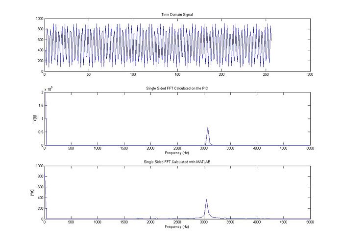
The final example is a 3 kHz sine wave. |
The final example is a 3 kHz sine wave. |
||
[[Image: FFT_3K_sin.jpg]] |
[[Image: FFT_3K_sin.jpg|border|700px]] |
||
Revision as of 12:49, 16 February 2010
Original Assignment
Do not erase this section!
Your assignment is to read in several cycles of a periodic signal from a function generator (e.g., a sine wave or a square wave), perform an FFT on your samples using your PIC32, and send back the results to a PC to display. Try this for 256 samples and 1024 samples, and determine how long it takes to compute the FFT for each, once you have collected the data. Verify that the results make sense according to the input signals you've used; for example, a sine wave should have all power at the chosen frequency, while a square wave will have much of the power at the frequency of the wave, but power at other frequencies, too.) Check out the MPLAB C32 Libraries manual to learn more about the dsplib_dsp.h, which you must include. Try both mips_fft16 and mips_fft32.
Overview
A fast Fourier transform (FFT) is a method to calculate a discrete Fourier transform (DFT). More information about FFTs and DFTs can be found on wikipedia (linked). The following circuit and code allow a user to put a signal into a PIC32, perform an FFT on that signal, output the data to Matlab via RS-232, and view a plot showing the raw signal, the FFT as calculated by the PIC, and the FFT as calculated by Matlab. Viewing the Matlab calculation is for verification only and can be commented out of the Matlab code.
Commented C code and Matlab code are provided at the bottom of this page and can be downloaded here.
Circuit
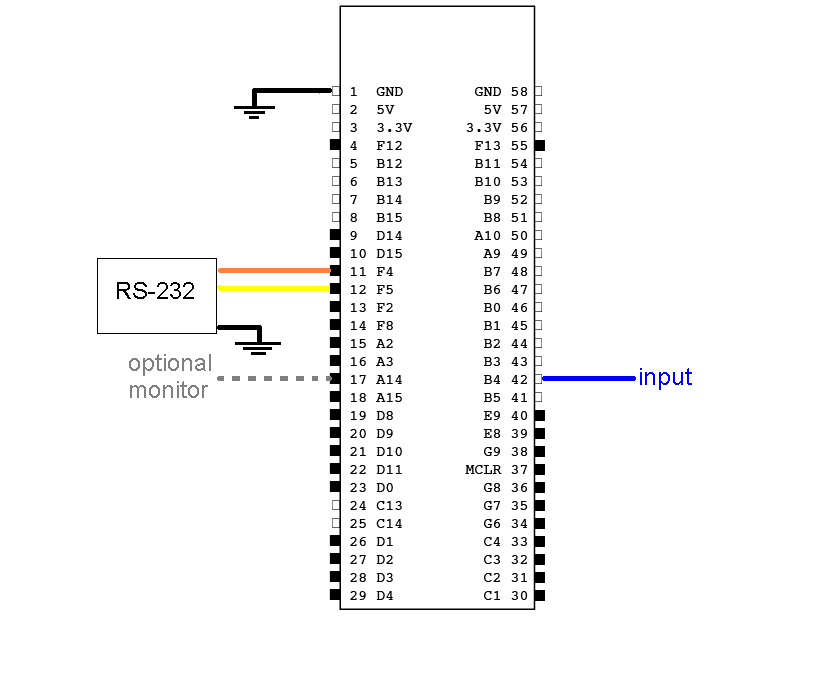
Beyond simple inputs and outputs, there is no special circuitry required for computing FFTs. The signal is inserted into pin B4 on the PIC and must be below VREF on the PIC (currently configured to 3.3 V). For data output, the PIC uses RS-232 communication. Three connections need to be made with the RS-232:
- Orange RS-232 wire to pin F4 on the PIC
- Yellow RS-232 wire to pin F5 on the PIC
- Black RS-232 wire to ground
The remaining connection is not essential for FFT caclulation but allows the user to monitor the calculation time. Pin A14 goes high during calculation and goes back low when the calculation is completed. This feature lets the calculation time be monitored on an oscilloscope.
The following circuit diagram illustrates the signal generator to PIC connection, the RS-232 connections, and the optional oscilloscope connection.
Code
The following is the source code to be programmed onto the PIC. If unfamiliar, see here for a guide to creating a .hex file with MPLAB and here for directions to load files to the PIC. It first establishes inputs, outputs and RS-232 communication. When prompted with a 'p' (as written, it is prompted automatically by Matlab), the PIC computes the FFT then sends the magnitude portion of the single-sided FFT and the raw samples to Matlab.
/* Sam Bobb,  Daniel Cornew,  Ryan Deeter
	Fast Fourier Transform (FFT) Example
	ME 333, Lab 5
	Feb 2010
*/

/** INCLUDES ***************************************************/
#include "HardwareProfile.h"
#include <plib.h>
#include "dsplib_dsp.h"
#include "fftc.h"


/** Constants **************************************************/

#define TRUE 		1
#define FALSE		0

#define LOOP_TIME_PIN		LATAbits.LATA14

#define DESIRED_BAUDRATE    	(19200)      // The desired BaudRate

// To modify the number of samples:
#define fftc fft16c256 //from fftc.h, for N = 256 use fft16c256, for N = 1024 use fft16c1024
#define N 256	// Also change the log2N variable below!!

// To modify the sampling frequency
#define SAMPLE_FREQ 10000
// Also change the timer interupt setup in initInterruptController!

/** Function Declarations **************************************/
void initInterruptController();

void initUART2(int pbClk);

void sendDataRS232(void);

void computeFFT(void);  //sets up function to compute FFT


/** Global Variables *******************************************/

int computeFFTflag = FALSE; //used to indicate that an fft computation has been requested over rs232

int sampleIndex = 0; //keeps track of where we're putting our ADC reading

/** establish variables for FFT calculation*/
// -----
// this has to be changed for different values of N
int log2N = 8; // log2(256) = 8
//int log2N = 10; // log2(1024) = 10
// -----

int16c sampleBuffer[N]; //initialize buffer to collect samples
int16c calcBuffer[N]; // initialize buffer to hold old samples
int16c scratch[N];
int16c dout[N]; //holds computed FFT until transmission

long int singleSidedFFT[N];
long int freqVector[N];

/** Main Function **********************************************/

int main(void)
{
	int	pbClk;
	int i;

	// Configure the proper PB frequency and the number of wait states
	pbClk = SYSTEMConfigPerformance(SYS_FREQ);

	TRISAbits.TRISA14 = 0;

	// Allow vector interrupts
	INTEnableSystemMultiVectoredInt();

	mInitAllLEDs();

	initInterruptController();

	initUART2(pbClk);

	// Configure the proper PB frequency and the number of wait states
	SYSTEMConfigPerformance(SYS_FREQ);

	// -------- Set Up ADC --------
	// configure and enable the ADC
	CloseADC10();	// ensure the ADC is off before setting the configuration

	// define setup parameters for OpenADC10
				// Turn module on | output in integer | trigger mode auto | enable  autosample
	#define PARAM1  ADC_MODULE_ON | ADC_FORMAT_INTG16 | ADC_CLK_AUTO | ADC_AUTO_SAMPLING_ON

	// define setup parameters for OpenADC10
				// ADC ref external    | disable offset test    | enable scan mode | perform 2 samples | use one buffer | use MUXA mode
	#define PARAM2  ADC_VREF_AVDD_AVSS | ADC_OFFSET_CAL_DISABLE | ADC_SCAN_ON | ADC_SAMPLES_PER_INT_2 | ADC_ALT_BUF_OFF | ADC_ALT_INPUT_OFF

	// define setup parameters for OpenADC10
	// 				  use ADC internal clock | set sample time
	#define PARAM3  ADC_CONV_CLK_INTERNAL_RC | ADC_SAMPLE_TIME_15

	// define setup parameters for OpenADC10
				// set AN4
	#define PARAM4	ENABLE_AN4_ANA

	// define setup parameters for OpenADC10
	// do not assign channels to scan
	#define PARAM5	SKIP_SCAN_AN0 | SKIP_SCAN_AN1 | SKIP_SCAN_AN2 | SKIP_SCAN_AN3 | SKIP_SCAN_AN5 | SKIP_SCAN_AN6 | SKIP_SCAN_AN7 | SKIP_SCAN_AN8 | SKIP_SCAN_AN9 | SKIP_SCAN_AN10 | SKIP_SCAN_AN11 | SKIP_SCAN_AN12 | SKIP_SCAN_AN13 | SKIP_SCAN_AN14 | SKIP_SCAN_AN15

	// use ground as neg ref for A | use AN4 (B4) for input A
	// configure to sample AN4
	SetChanADC10( ADC_CH0_NEG_SAMPLEA_NVREF); // configure to sample AN4
	OpenADC10( PARAM1, PARAM2, PARAM3, PARAM4, PARAM5 ); // configure ADC using parameter define above

	EnableADC10(); // Enable the ADC

	while ( ! mAD1GetIntFlag() ) { } // wait for the first conversion to complete so there will be valid data in ADC result registers
	// ------ DONE SETTING UP ADC ------

	// zero the freqVector and singleSidedFFT
	for (i=0; i<N; i++)
	{
		freqVector[i] = 0;
		singleSidedFFT[i] = 0;
	}

	// generate frequency vector
	// this is the x-axis of your single sided fft
	for (i=0; i<N/2; i++)
	{
		freqVector[i] = i*(SAMPLE_FREQ/2)/((N/2) - 1);
	}

	// wait around until you get an fft command from rs232
	// then call computeFFT to generate an fft of the last block of samples
	// then send out rs232.
	// If you want to use FFT without rs232, you can call computeFFT when ever you want in your program.
	while(1)
	{
		if (computeFFTflag == TRUE)
		{
			computeFFT();
			sendDataRS232();
		}
	}

	CloseOC1();


} //end main


/** Interrupt Handlers *****************************************/
// interrput code for the timer 3
void __ISR( _TIMER_3_VECTOR, ipl7) T3Interrupt( void)
{
	int i;
	//LOOP_TIME_PIN = TRUE;
	// When we used the loop time pin to measure the length of this ISR,
	// we measured 400 ns, so you could sample at over 1 MHz.

	sampleBuffer[sampleIndex].re = ReadADC10(0); // read the ADC into the real part of the samplebuffer
	sampleBuffer[sampleIndex].im = 0; // the imaginary value is 0.

	// you could shave a little time off this ISR by just zeroing the .im value once, outside the ISR

	// increment the sampleIndex
	if (sampleIndex == (N-1))
	{
		sampleIndex = 0;
	}
	else
	{
		sampleIndex++;
	}


	//LOOP_TIME_PIN = FALSE;

	// clear interrupt flag and exit
	mT3ClearIntFlag();
} // T3 Interrupt


// UART 2 interrupt handler
// it is set at priority level 2
void __ISR(_UART2_VECTOR, ipl2) IntUart2Handler(void)
{
	char data;

	// Is this an RX interrupt?
	if(mU2RXGetIntFlag())
	{
		// Clear the RX interrupt Flag
		mU2RXClearIntFlag();

		data = ReadUART2();
		// Echo what we just received.
		putcUART2(data);

		switch(data)
		{

			case 'p': // compute and output the FFT
				computeFFTflag = TRUE;
				break;
		}

		// Toggle LED to indicate UART activity
		mLED_0_Toggle();

	}

	// We don't care about TX interrupt
	if ( mU2TXGetIntFlag() )
	{
		mU2TXClearIntFlag();
	}
}


/** Other Functions ********************************************/

void initInterruptController(void)
{
	// init Timer3 mode and period (PR3)
	OpenTimer3( T3_ON | T3_PS_1_1 | T3_SOURCE_INT, 0x1F40); // produces 100 ms period
															// sampling frequency = 10 kHz

	mT3SetIntPriority( 7); 	// set Timer3 Interrupt Priority
	mT3ClearIntFlag(); 		// clear interrupt flag
	mT3IntEnable( 1);		// enable timer3 interrupts
}

void initUART2(int pbClk)
{
	 // define setup Configuration 1 for OpenUARTx
		// Module Enable
		// Work in IDLE mode
		// Communication through usual pins
		// Disable wake-up
		// Loop back disabled
		// Input to Capture module from ICx pin
		// no parity 8 bit
		// 1 stop bit
		// IRDA encoder and decoder disabled
		// CTS and RTS pins are disabled
		// UxRX idle state is '1'
		// 16x baud clock - normal speed
	#define config1 	UART_EN | UART_IDLE_CON | UART_RX_TX | UART_DIS_WAKE | UART_DIS_LOOPBACK | UART_DIS_ABAUD | UART_NO_PAR_8BIT | UART_1STOPBIT | UART_IRDA_DIS | UART_DIS_BCLK_CTS_RTS| UART_NORMAL_RX | UART_BRGH_SIXTEEN

	 // define setup Configuration 2 for OpenUARTx
		// IrDA encoded UxTX idle state is '0'
		// Enable UxRX pin
		// Enable UxTX pin
		// Interrupt on transfer of every character to TSR
		// Interrupt on every char received
		// Disable 9-bit address detect
		// Rx Buffer Over run status bit clear
	 #define config2		UART_TX_PIN_LOW | UART_RX_ENABLE | UART_TX_ENABLE | UART_INT_TX | UART_INT_RX_CHAR | UART_ADR_DETECT_DIS | UART_RX_OVERRUN_CLEAR

	// Open UART2 with config1 and config2
	OpenUART2( config1, config2, pbClk/16/DESIRED_BAUDRATE-1);	// calculate actual BAUD generate value.

	// Configure UART2 RX Interrupt with priority 2
	ConfigIntUART2(UART_INT_PR2 | UART_RX_INT_EN);
}


void sendDataRS232()
{
	int i;
	char RS232_Out_Buffer[32]; // max characters per line (line feed and carriage return count)

	sprintf(RS232_Out_Buffer,"\n\rSTART\n\r"); //print START. MATLAB uses this as a start delimiter
	putsUART2(RS232_Out_Buffer);

	sprintf(RS232_Out_Buffer,"ROWS=%d\n\r", N); //print the number of rows, so matlab can make the correct sized buffer
	putsUART2(RS232_Out_Buffer);

	for(i = 0; i < N; i++)
	{
		// output: frequency vector, the calculated fft, raw samples
		sprintf(RS232_Out_Buffer,"%d %d %d\n\r",freqVector[i], singleSidedFFT[i], calcBuffer[i].re);
		putsUART2(RS232_Out_Buffer);
	}

	sprintf(RS232_Out_Buffer,"END\n\r"); //output end so matlab knows we're done
	putsUART2(RS232_Out_Buffer);

}


void computeFFT()
{
	// when using 256 samples, we measured this function to take about 500 microseconds
	// (not including the time to send rs232 data)
	int i;

	mT3IntEnable(0); //turns off interrupt while computing FFT

	LOOP_TIME_PIN = TRUE;

	for (i=0; i<N; i++)
	{
		if (i<sampleIndex)
		{
			// old chunk
			calcBuffer[i+(N-sampleIndex)] = sampleBuffer[i];
		}
		else // i >= sampleIndex
		{
			// new chunk
			calcBuffer[i-sampleIndex] = sampleBuffer[i];
		}

	}

	// load complex input data into din
	mips_fft16(dout, calcBuffer, fftc, scratch, log2N);

	// compute single sided fft
	for(i = 0; i < N/2; i++)
	{
		singleSidedFFT[i] = 2 * ((dout[i].re*dout[i].re) + (dout[i].im*dout[i].im));
	}

	LOOP_TIME_PIN = FALSE;

	computeFFTflag = FALSE;

	// do something with dout
	mT3IntEnable(1); //turn interrupt back on
}
The following Matlab code computes its own FFT with the raw samples. It then plots the input signal, the PIC calculated FFT, and the Matlab calculated FFT, for comparison.
% fftserial interface v 2

%Sam Bobb, Daniel Cornew, Ryan Deeter
%ME 333 Lab 5: FFT of Analog Input, Winter 2010

%This code receives the single sided magnitude FFT calculated on the PIC
%and the raw samples through serial communication.  Matlab calculates its
%own FFT of the raw samples, then plots the input signal, PIC calculated
%FFT, and Matlab calculated FFT.


Fs = 10000;                    % Sampling frequency
T = 1/Fs;                     % Sample time
L = 256;                     % Length of signal
t = (0:L-1)*T;                % Time vector


%for runtimes=1:100      %UNCOMMENT FOR CONTINUOUS FFT

columns = 3;

%check if the serial port already exists
%if it does, close it, it probably means something bad happened last run
if exist('COM','var')
    disp('closing old port instance');
    fclose(COM)
    delete(COM)
    clear COM
    disp('port closed');
end

% open the serial port
COM = serial('COM6');
set(COM,'BaudRate',19200);
fopen(COM)

disp('port opened');

% send the command to print data
fprintf(COM,'p')


%there's usually some garbage at the beginning (like the echoed p
%character command and line  breaks); this reads lines in until we find
%the start line
text = fscanf(COM, '%s');
while isempty(strfind(text, 'START'))
    text = fscanf(COM, '%s');
end


% read number of rows
rowstext = fscanf(COM, '%s');
pat = 'ROWS=';
split = regexp(rowstext, pat, 'split');
rows = str2double(split(2));

DATA = zeros(rows,columns);

%generate the fscanf format argument
%repeate the formatchar character for the number of columns
formatchar = '%d';
serialpat = '';

%establishing fscanf format
for j = 1:columns
    serialpat = [serialpat ' ' formatchar];
end

%reads serial data and puts it into DATA
for j = 1:rows
    DATA(j, :) = fscanf(COM, serialpat, [columns 1]);
    %disp(COM.BytesAvailable)

end

%reads last line
last = fscanf(COM, '%s');

%verifies that last line read is the last line
if strcmp(last,'END')
    disp('Success')
else
    disp('Problem')
end

%disp(COM.BytesAvailable)       %for debugging

%plotting input signal
subplot(3, 1, 1)
plot(DATA(:,3))
title('Time Domain Signal')

%plotting PIC calculated FFT
subplot(3, 1, 2)
plot(DATA(:,1), DATA(:,2))
title('Single Sided FFT Calculated on the PIC')
xlabel('Frequency (Hz)')
ylabel('|Y(f)|')
axis([0 Fs/2 0 2e5])

%calculating FFT in Matlab
NFFT = 2^nextpow2(L); % Next power of 2 from length of y
Y = fft(DATA(:,3),NFFT)/L;

%Y = DATA(:,1) + DATA(:,2)*1i;

f = Fs/2*linspace(0,1,NFFT/2+1);

% Plot Matlab's single-sided amplitude spectrum.
subplot(3, 1, 3)
plot(f,2*abs(Y(1:NFFT/2+1)))
title('Single Sided FFT Calculated with MATLAB')
xlabel('Frequency (Hz)')
ylabel('|Y(f)|')

%pause(2)        %UNCOMMENT FOR CONTINOUS FFT

%end             %UNCOMMENT FOR CONTINUOUS FFT

%closes serial port
fclose(COM)
delete(COM)
clear COM
disp('port closed');
Example Plots
Here is an example using a 500 Hz sine wave input.
This example uses a 1 kHz sine wave.
This example is still at 1 kHz, but with a square wave.
This example shows a 2 kHz sine wave.
