Difference between revisions of "Actuators Available in the Mechatronics Lab"
| Line 207: | Line 207: | ||
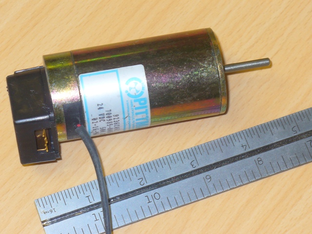
===Pittman 700935 motor with 500 line encoder=== |
===Pittman 700935 motor with 500 line encoder=== |
||
[[image: |
[[image:Pittmann700935.jpg|right]] |
||
* Speed: 5000 RPM |
* Speed: 5000 RPM |
||
| Line 214: | Line 214: | ||
* Encoder: 500 CPR 2 channel encoder, 2000 CPR in 4X mode at output shaft |
* Encoder: 500 CPR 2 channel encoder, 2000 CPR in 4X mode at output shaft |
||
* Gearhead: N/A |
* Gearhead: N/A |
||
* Weight: unknown |
|||
* Length: unknown |
|||
* Motor Constant: unknown |
|||
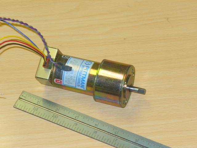
===Pittman GM9413J820 motor with 500 line encoder=== |
|||
[[image:PittmannGM9413J820.jpg|right]] |
|||
* Speed: 85 RPM |
|||
* Voltage: 24 V |
|||
* Torque: unknown |
|||
* Encoder: 500 CPR 2 channel encoder, 39,400 CPR in 4X mode at output shaft |
|||
* Gearhead: 19.7:1 |
|||
* Weight: unknown |
* Weight: unknown |
||
* Length: unknown |
* Length: unknown |
||
Revision as of 16:38, 3 June 2009
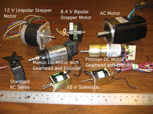
We have acquired a number of actuators that are appropriately sized for many mechatronics projects. These are the "standard" lab actuators. You are welcome to borrow them for your project and return them when you are finished. In addition to the actuators mentioned below, we have a number of other actuators that we have acquired over the years that you are welcome to borrow.
For your particular project, it may be best to spec out and buy a particular type and size of actuator. If your specifications are not too critical, however, the actuators below will allow you to get started right away.
DC Motors (with gearheads and encoders)
There are many types of DC motors, but our favorites are brushed permanent magnet DC motors for their power, price, ubiquity, and simplicity. Simply put a voltage across the two motor terminals, and the motor spins. (You can learn about the theory of how a brushed DC motor works and suggested methods for driving a DC motor elsewhere on this wiki.)
One problem is that most DC motors tend to rotate at very high speeds, typically several thousand RPM or more. This is too fast for most mechatronics applications. Also, they tend to have too little torque. Both of these problems can be solved by the use of gears on the output shaft of the motor. If the motor has an N:1 gearhead on its output shaft (where N>1, typically), then the output shaft of the gearhead reduces the speed of the motor by a factor of N and increases the torque of the motor by a factor of N. (You can learn more about how gears work including other issues they introduce, such as gearhead efficiency and backlash.)
Another issue is how to determine how far the motor has rotated. You need feedback from the motor. There are many ways to do this, using encoders, potentiometers, and tachometers. The most common way to get angle feedback is through the use of encoders. An encoder is typically attached to a motor shaft and produces pulses that encode the shaft rotation angle. These pulses can be read in by the encoder inputs of the Mechatronics Lab PC/104 stacks.
So, perhaps the most versatile kind of actuator is a DC motor with a gearhead and an encoder. Below are some that we keep in the lab. Sometimes DC motors with gearheads and encoders can be purchased through surplus outlets at great prices, for prices less than any of the single components (motor, gearhead, encoder) could be purchased individually. That's how many copies of the actuators below were purchased. If you see a great deal on a nice-sized motor plus gearhead plus encoder, of which many copies can be purchased, let us know!
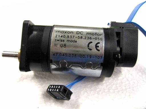
6W Maxon motor with 6:1 gearhead and 100 line encoder
Summary:
- 24 V, 41.5 ohms resistance, max current 0.58 Amps
- max torque: 0.15 Nm (approx)
- max speed: 600 RPM (approx)
- encoder: 600 counts/rev at output shaft, 2400 counts/rev in 4x decoding mode
The motor is rated at 24 volts, giving a no-load (maximum) speed of 3990 RPM (about 418 radians/sec) and a (maximum) stall torque of 31.9 mNm (milli Newton meters). The terminal resistance (the resistance through the motor windings) is 41.5 ohms. This means if you put 24 V across it, the maximum current that it will draw is 24/41.5 = 0.58 Amps. This maximum current occurs when the motor is stalled and generating its maximum torque. Motor torque is proportional to the motor current by the constant of proportionality called the torque constant, which is different for every motor.
The motor is called a 6 Watt motor because that is the maximum electrical power (current times voltage) that can be put into the motor on a continuous basis. Beyond this power level, the amount of power dissipated by the resistance of the motor windings will cause the windings to heat up unacceptably. (It is fine to overpower the motor intermittently, allowing the coils to cool so that the average power does not exceed the rated power.) At this operating point, the motor draws 244 mA, giving 24 V x 0.244 A = 5.86 W electrical input power. At this operating point, the speed of the motor is approximately 1689 RPM, or 177 radians/sec, and the torque of the motor is 13.5 mNm, giving 177 rad/sec x 0.0135 Nm = 2.39 W of mechanical output power, giving a power-conversion efficiency of about 41% at this operating point. The maximum efficiency of the motor is 70%, which occurs at a higher speed and lower torque. The maximum mechanical power you can get out of the motor is (1/2 max torque) x (1/2 max speed) = 3.33 W. This is beyond the continuous operation recommendation, but it is fine to run it for short periods at this operating point.
Often you will want to run the motor at lower voltages, for instance at 12 V, instead of the rated 24 V. In this case just multiply the max current, speed, and torques by the factor 12/24 = 1/2. In particular, the maximum output power will be only (1/2) x (1/2) = 1/4 the maximum at 24 V.
This actuator comes with a 6:1 spur gearhead, which increases the torque available at the gearhead's output shaft by a factor of 6 and decreases the speed by a factor of 6. (In this ideal case, the power at the gearhead's output shaft is equal to the power at the input. In practice, gearheads have an efficiency also; the maximum efficiency of the gearhead here is 81%. This reduces the torque available.)
In summary, then, if your application requires no more than about 6 x 31.9 mNm = 0.19 Nm maximum torque, 3990 RPM / 6 = 665 RPM max speed, and 3.3 W max mechanical power, this may be the motor for you. Reduce those values by a factor of 1/2, 1/2, and 1/4, respectively, if you are operating the motor with 12 V max instead of 24 V max.
This actuator also comes with a 100 line single-ended incremental optical encoder, with outputs A+ and B+. There is no index channel. The encoder is attached to the motor. Each of the A+ and B+ channels makes 100 pulses per revolution of the motor, or 6 x 100 = 600 pulses per revolution of the output shaft of the gearhead. This means the encoder provides 360 deg / 600 pulses = 0.6 deg/pulse resolution when the pulses are decoded with the 1x scheme, or 0.15 deg/pulse resolution with the 4x decoding scheme.
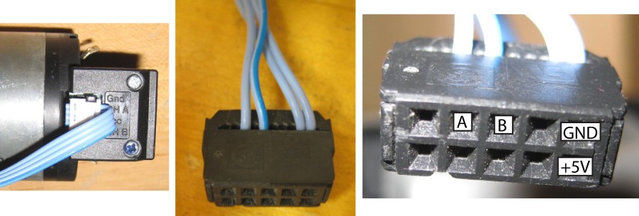
Information about the Maxon motor is given in this data sheet which includes other motors in this family (ours is the 24V version) and this data sheet which gives only the information on this motor. Information on the 6:1 gearhead can be found here. The encoder pin-out is indicated below:
The encoder comes with a 4-connector ribbon cable, corresponding to GND, Channel A, Vcc (usually +5V), and Channel B, as shown on the left. Here the ribbon cable is broken out into a 10-pin connector (which we have in the lab). The connector above is made to work with the PC/104 stacks, and the pin-out is shown. Always make sure you have the right connections for your encoder so you don't damage it!
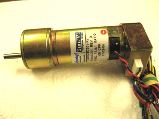
Pittman GM8224 motor with 19.5:1 gearhead and 500 line encoder
If you need more power than the motor above, this gearmotor may be a good choice. As an added bonus, it provides much higher encoder resolution.
Summary:
- 24 V, 4.33 ohms resistance, max current 5.54 Amps
- max torque: 2 Nm (approx)
- max speed: 500 RPM (approx)
- encoder: 9750 counts/rev at output shaft, 39,000 counts/rev in 4x decoding mode
This motor is also rated at 24 V, with a terminal resistance of 4.33 ohms, giving a stall (maximum) current of 5.54 Amps. The stall torque of the motor itself is 0.1186 Nm and the no-load (maximum) speed is 10,158 RPM (1064 radians/sec). The recommended maximum continuous torque is 0.0185 Nm which occurs at 8573 RPM (898 radians/sec). Taken together, the maximum motor mechanical power is (1/2 Tmax) x (1/2 nmax) = 31.5 W and the maximum recommended continuous mechanical power is 16.6 W. The maximum electrical input power occurs when the motor is stalled (or starting) and is 24 V x 5.54 A = 133 W. If you operate the motor at a smaller voltage V2, then multiply the currents, speeds, and torques above by a factor V2/24 and the power by a factor of (V2/24)^2.
This motor has a 19.5:1 gearhead with a power conversion efficiency of 73%. Ignoring the efficiency for the moment, the 19.5:1 gearbox means that this actuator may be appropriate if our application calls for no more than a maximum speed of 10,158 RPM / 19.5 = 521 RPM and a maximum torque of 0.1186 Nm x 19.5 = 2.3 Nm. In other words, the output shaft speed is similar to the Maxon gearmotor above, but with about 10 times the torque.
This motor comes with a 500 line encoder attached to the motor shaft. The encoder has output channels A+ and B+ (no index pulse). This means that the encoder provides 500 x 19.5 = 9750 pulses per revolution of the output shaft. In the 4x decoding mode, this gives 39,000 counts per revolution, or a resolution of 360/39,000 = 0.00923 degrees.
We also have a limited number of Pittman GM8712 motors with a 19.5:1 gearhead and 512 line encoder. These motors are also rated at 24V but have a higher terminal resistance of 12.1 ohms, giving a maximum current of 24/12.1 = 1.99 Amps. They have a maximum speed of 7847 RPM and maximum torque of 0.052 Nm before the gearhead, or (ignoring gearhead efficiency) 402 RPM and 1.01 Nm after the gearhead. This motor is less powerful and draws less current, which may be appropriate for some applications. The encoder provides 9984 pulses per revolution of the output shaft of the gearhead, or 360/(4 x 9984) = 0.009 degrees resolution in 4x decoding mode.
See the data sheet for more detailed information on these Pittman 8224 and 8712 gearmotors. The 8712 is not treated explicitly, but is believed to be similar to the 8722.
The quadrature encoder has four wires: black (GND), red (+5V), and blue and yellow as channels A and B.
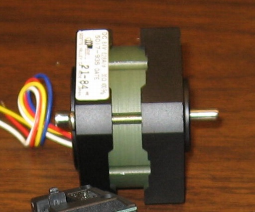
Pittman 700935 motor with 500 line encoder
- Speed: 5000 RPM
- Voltage: 24 V
- Torque: unknown
- Encoder: 500 CPR 2 channel encoder, 2000 CPR in 4X mode at output shaft
- Gearhead: N/A
- Weight: unknown
- Length: unknown
- Motor Constant: unknown
Pittman GM9413J820 motor with 500 line encoder
- Speed: 85 RPM
- Voltage: 24 V
- Torque: unknown
- Encoder: 500 CPR 2 channel encoder, 39,400 CPR in 4X mode at output shaft
- Gearhead: 19.7:1
- Weight: unknown
- Length: unknown
- Motor Constant: unknown
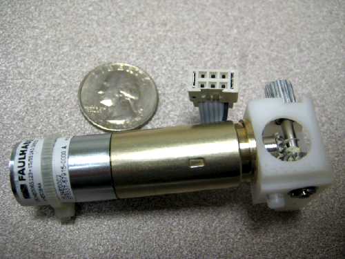
Faulhaber 1524E006S motor with 141:1 gearhead and HES164A magnetic quadrature encoder
Summary:
- motor rated at 6V, 12 ohms resistance (motor: 1524E006S123, where 123 is a special order)
- 141:1 gearhead (gearhead: 15/5S141:1K832)
- max speed at 6V: approximately 80 RPM at gearhead output
- quadrature encoder with 1 line per motor revolution, or 141 x 4 = 564 counts/rev at output shaft in 4x decoding mode (encoder: HES164A)
This little motor is the right size, speed, and torque for small wheeled mobile robots. Ours were bought surplus from bgmicro.com. This page by David Cook has a lot of great information on this motor + gearhead + encoder combination. More info can be found in this data sheet from Faulhaber, though our exact model encoder and motor are not listed. The gearhead has a right-angle drive at the output.
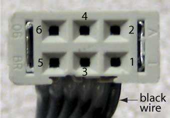
The pins on the connector are (see figure at right):
1. Motor +
2. +5V (or similar) to power the encoder
3. Encoder channel A
4. Encoder channel B
5. GND for the encoder
6. Motor -
Encoder channels A and B can sink (connect to ground) up to probably 25mA like most Hall sensors. There is only a a weak pull-up resistor inside, perhaps 10K, so they can only source (connect to +5) about 2mA. If you find the logic high signal from the encoder channel is not close enough to +5, which can happen even due to loading by an LED, you may want to add an external pull-up resistor from each encoder channel to +5. 470ohms is a good choice.
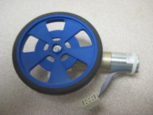
These wheels can be used with the motor (with the right-angle drive) if you drill out the center of the wheel with a 9/32" bit (approximately). Then you should get a nice tight press-fit. We have some of these wheels in the lab. This press-fit is not suitable for high-torque applications, though; the shaft may begin to slip.
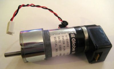
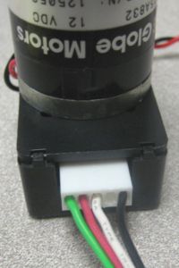
Globe motor with 187.68:1 gearhead and 500 line encoder
Summary:
- motor rated at 12V, 21 ohms resistance (0.57 A stall current)
- 187.68:1 gearhead for high torque and low speed
- max speed at 12V: approximately 17 RPM at gearhead output (no load speed, motor alone: approx 3000 RPM)
- torque constant (motor alone): approximately 34 mNm/A (or 3.6 mV/RPM)
- stall torque: motor alone: 0.019 Nm; with gearhead 2.4 Nm (based on torque multiplier of 125, less than the 187 gear ratio due to efficiency losses)
- quadrature encoder with 500 lines per motor revolution, or 500 x 4 x 187.68 = 375,360 counts/rev at output shaft in 4x decoding mode (encoder: HEDS-5505 A04)
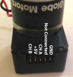
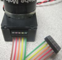
This small motor combines with a high resolution encoder and a high gear ratio gearbox to give a high torque, low speed actuator with high resolution position sensing (and velocity sensing by finite differencing). The stall torque for this gearmotor (at 12 V) is approximately the same as that for the Pittman GM8224 gearmotor (at 24 V), but the max speed for the PIttman gearmotor is 20 times higher. The pin-out for the encoder is shown below. You can attach to the encoder using a Samtec IDSS-05-D-12.00 cable (shown in the middle below; order directly from Samtec, about $3.50 each and we have several in the lab), a less-expensive 5-pin cable CAB2154 from bgmicro (we have several in the lab), or you can make your own cable using stranded wires (22 AWG or ribbon cable) crimped or soldered in female Molex terminal pins (Molex series KK 2759, part number WM1114CT-ND on digikey) in a Molex 5 position connector housing (Molex series KK 2695, part number WM1578-ND on digikey), shown at right below. (See Making a Molex Connector for more details.) The datasheet for the encoder recommends putting a 3.2k pull-up resistor on Channels A and B (i.e., 3.2k resistors from these lines to +5V). The encoder works without these, but the datasheet indicates that you get better rise times on the encoder signals at high speeds when the pull-up resistors are added.
If you want a higher-speed (up to 3000 RPM at 12V) lower-torque actuator, you can try removing the gearbox. This task takes a bit of work and may require a bit of machining. See here. This page also shows how to remove the encoder, in case you want to use it in a project without the motor.
The two motor power leads are wound through a ferrite toroid to suppress EMI "noise."
Here you can find a cad file describing this actuator, a datasheet for the encoder, and a datasheet for the Samtec IDSS-05-D-12.00 connector.
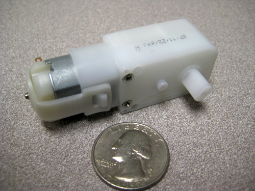
GM3 and GM9 Gearmotors
Summary: (GM3 pictured at right)
- rated at 6V, approx 10 ohms resistance
- 224:1 gearhead (GM3) or 143:1 gearhead (GM9)
- max speed at 6V approximately 43 RPM (GM3) or 84 RPM (GM9)
- stall torque at 6V approximately 73 oz-in (GM3) or 52 oz-in (GM9)
- no encoder installed, but can be modified to add one; see here
- size: 70 x 22.5 x 37 mm
These highly-geared motors can be bought new at solarbotics.com or hobbyengineering.com. These motors work with these wheels, which we have in the lab. The motors do not come with encoders, but you can add one yourself, similar to the magnetic encoder on the Faulhaber motor above.
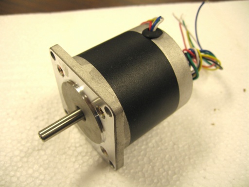
Stepper Motors
Stepper motors move in discrete steps. The controller energizes electromagnet coils, and the motor's rotor rotates to the nearest equilibrium point. By proper sequencing of which coils are energized, the motor rotates as desired (and, if the rotation is fast enough, may simply pass through the equilibrium points without stopping).
One nice thing about stepper motors is that they do not require feedback; we know how far the motor has rotated, because we commanded the motion. This becomes a problem if we try to rotate the motor too fast, or if the load is larger than expected --- the motor may not actually do what we commanded. Stepper motors are a good choice for relatively low-torque applications where the loads are consistent, so we can be assured our commanded motions are followed.
Jameco 163395 8.4V bipolar stepper motor
Although this motor is rated at 8.4V, it is possible to run it at lower or slightly higher voltages.
- 1.8 deg/step (0.9 deg/half step)
- 8.4V, 2 phases, 30 ohms resistance, 280 mA current
- holding torque: 0.081 Nm (coils energized)
- detent torque: 0.0037 Nm (coils off)
- size: 1.64" motor diameter, 1.2" motor height
- shaft: 0.29" x 0.155" diameter
- mass: 0.24 kg
More information can be found on this data sheet. There are four leads, two for each independent coil.
Jameco 162026CX 12V unipolar stepper motor
If you need more holding torque, this stepper may be a good choice.
- 1.8 deg/step (0.9 deg/half step)
- 12V, 4 phases, 20 ohms resistance, 600 mA current
- holding torque: 0.588 Nm (coils energized)
- detent torque: 0.071 Nm (coils off)
- size: 2.2" motor diameter, 2.0" motor height
- shaft: 1" x 0.25" diameter
- mass: 0.65 kg
More information can be found on this data sheet (ours is the 57BYG084). There are six leads, three for each independent coil.
RC Servo Motors
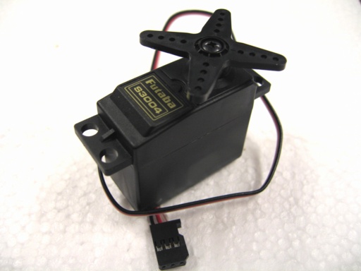
RC servos are convenient for positioning applications that require significant torque, not much speed, and only moderate positioning precision. They take three connections, power (+5V, typically), ground, and a pulsing signal that tells the motor the desired angle (typically a pulse of 0.5 - 3 ms every 20 ms or so, where the duration of the pulse indicates the desired angle of the motor). Inside the motor is a potentiometer that senses the actual angle of the motor output shaft and a feedback controller that tries to make the motor angle match that specified by the pulsed signal. There is also a large gear ratio such that the motor provides high torque at low speed. Most RC servos have limited angle range, like 180 degrees, due to the angle-sensing potentiometer.
Futaba S3004 standard ball bearing RC servo motor
- motor rotation: 180 degrees
- speed: 60 degrees in 0.23 sec at 4.8V, 0.19 sec at 6V
- torque: 0.31 Nm at 4.8V, 0.4 Nm at 6V
- size: 1.4" height, 0.8" width
- mass: 37.2 g
These were purchased from Tower Hobbies, part number LM1954. Higher torque versions are also available.
Solenoids
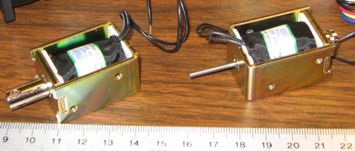
Solenoids are simple on-off actuators consisting of a plunger moving in an electromagnetic field. If you power the electromagnet, the plunger is "pushed" or "pulled" a particular stroke length, and if you unpower the coil, the plunger returns to its original position, usually by a return spring or gravity. These are simple to control and useful for applications where the actuator only has to take one of two positions.
We stock two solenoids (in addition to many random ones) which are basically
the same, except one is a "pull type" solenoid and the other is a "push type."
Jameco 262262 (pull) and 262271 (push) 12V open frame solenoid
- 12 V, 36 ohm resistance, 333 mA
- holding force: 0.5 N
- stroke: 6 mm
- size: 1.5" length x 1.0" x 0.8" diameter
- shaft diameter: 0.310"
- mass: 96 g
You can find a data sheet here. You can attach a lever (or other mechanical transformer) to the plunger to get more stroke and less force, or more force and less stroke. If no lever will meet your specs, then you will need another solenoid.
AC Motors
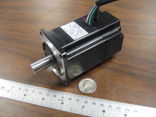
Some projects need more power than any of the actuators above can provide. In that case, you may be able to use a Yaskawa AC motor. These are technically in the Laboratory for Intelligent Mechanical Systems, but they are available for Mechatronics use. These should not be a first choice, as (1) they can be dangerous due to their high power, and (2) they limit the mobility of your project as they must be plugged into the wall to get 110V AC. You can find information on these motors and their amplifiers here.
