Difference between revisions of "Automated Xylophone"
Jenny Yong (talk | contribs) |
Jenny Yong (talk | contribs) |
||
| (7 intermediate revisions by the same user not shown) | |||
| Line 4: | Line 4: | ||
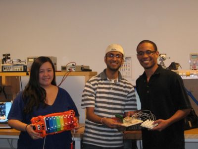
[[Image:AutomatedXylophoneGroup.jpg|thumb|400x400 px|right|From L to R: Jenny, Neil and Brandon]] |
[[Image:AutomatedXylophoneGroup.jpg|thumb|400x400 px|right|From L to R: Jenny, Neil and Brandon]] |
||
*Brandon Robins (Senior in Mechanical Engineering and Music Performance, Northwestern University) <br> |
*Brandon Robins (Senior in Mechanical Engineering and Music Performance, Northwestern University) <br> |
||
*Neil Tiwari (Masters Student in Biomedical Engineering |
*Neil Tiwari (Masters Student in Biomedical Engineering, Northwestern University) <br> |
||
*Jenny Yong (Senior in Mechanical Engineering, Northwestern University) <br> |
*Jenny Yong (Senior in Mechanical Engineering, Northwestern University) <br> |
||
<br> |
|||
<br> |
|||
<br> |
|||
<br> |
<br> |
||
<br> |
<br> |
||
| Line 30: | Line 27: | ||
<br> |
<br> |
||
Click [[ME 333 final projects|here]] to check out other Mechatronics projects! |
Click [[ME 333 final projects|here]] to check out other Mechatronics projects! |
||
<br> |
|||
<br> |
|||
<br> |
|||
<br> |
<br> |
||
<br> |
<br> |
||
| Line 53: | Line 47: | ||
<br> |
<br> |
||
<br> |
<br> |
||
| ⚫ | |||
=== Edit Mode === |
=== Edit Mode === |
||
| ⚫ | |||
To enter edit mode, you hit button *. Edit mode allows you to store about 250 notes, including rests, per block. Once you first enter edit mode, you must select which block you would like to store your collection of notes. To increase the block number, use button C. Button 9 will decrease the block number. Once you have selected your block, you hit the enter button, button D. Now, you are ready to begin programming notes. <br> |
To enter edit mode, you hit button *. Edit mode allows you to store about 250 notes, including rests, per block. Once you first enter edit mode, you must select which block you would like to store your collection of notes. To increase the block number, use button C. Button 9 will decrease the block number. Once you have selected your block, you hit the enter button, button D. Now, you are ready to begin programming notes. <br> |
||
<br> |
<br> |
||
As in real time mode, the first two rows of buttons still determine which note to program. Buttons 7 and 8 will adjust the note duration to longer and shorter respectively. Buttons 9 and C will adjust the which sequential number is being programmed. As with determining block number, button C increases the note number and button 9 will decrease the note number. Rests can be programmed using button #. To enter and store a note, you use the enter button, button #. Once you have finished entering the string of notes you would like to store, you hit button 0. Hitting this button will bring you to playback mode. <br> |
As in real time mode, the first two rows of buttons still determine which note to program. Buttons 7 and 8 will adjust the note duration to longer and shorter respectively. Buttons 9 and C will adjust the which sequential number is being programmed. As with determining block number, button C increases the note number and button 9 will decrease the note number. Rests can be programmed using button #. To enter and store a note, you use the enter button, button #. Once you have finished entering the string of notes you would like to store, you hit button 0. Hitting this button will bring you to playback mode. <br> |
||
<br> |
<br> |
||
=== Playback Mode === |
=== Playback Mode === |
||
The user enters playback mode after going through edit mode. You can enter playback mode without having actually programmed anything in edit mode by simply pressing the 0 button after having entered edit mode. Once you are in playback mode, you select which block you would like to play similar to how you programmed which box you would like to edit. Button C will increase the block number, button 9 will decrease the block number. To select the block and play the stored notes, you hit the # button. <br> |
The user enters playback mode after going through edit mode. You can enter playback mode without having actually programmed anything in edit mode by simply pressing the 0 button after having entered edit mode. Once you are in playback mode, you select which block you would like to play similar to how you programmed which box you would like to edit. Button C will increase the block number, button 9 will decrease the block number. To select the block and play the stored notes, you hit the # button. <br> |
||
| Line 870: | Line 866: | ||
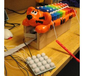
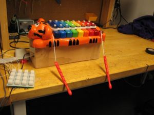
[[Image:AutomatedXylophonePic2.jpg|thumb|300x300 px|right|Automated Xylophone]] |
[[Image:AutomatedXylophonePic2.jpg|thumb|300x300 px|right|Automated Xylophone]] |
||
=== Results === |
=== Results === |
||
Our Automated Xylophone operated as expected, with full capability in both real time mode, edit mode and playback Mode. We were also able to get excellent sound on our xylophone. A video of our Automated Xylophone playing in real time mode can be found here. A video of our Automated Xylophone playing in playback mode can be found here.<br> |
Our Automated Xylophone operated as expected, with full capability in both real time mode, edit mode and playback Mode. We were also able to get excellent sound on our xylophone. A video of our Automated Xylophone playing in real time mode can be found [http://www.youtube.com/watch?v=_ubpAEyq9kg here]. A video of our Automated Xylophone playing in playback mode can be found [http://www.youtube.com/watch?v=QUSQOINeglQ here] with vies of the LCD screen during playback mode [http://www.youtube.com/watch?v=bwAo6oKskMs here].<br> |
||
<br> |
<br> |
||
<br> |
<br> |
||
Latest revision as of 08:30, 20 March 2009
Team Members
- Brandon Robins (Senior in Mechanical Engineering and Music Performance, Northwestern University)
- Neil Tiwari (Masters Student in Biomedical Engineering, Northwestern University)
- Jenny Yong (Senior in Mechanical Engineering, Northwestern University)
Overview
The goal of this project was to have a user input a sequence of notes and have a PIC controlled solenoid system hit a xylophone to generate tones. Our Automated Xylophone operates in two settings -- real time mode and playback mode. In real time mode, the user inputs notes using the keypad and they get played back on the xylophone instantaneously. In edit mode, a user can use the keypad and LCD screen to verify and store over 250 notes in sequence including rests to be played back on the xylophone while in playback mode.
Click here to check out other Mechatronics projects!
Operating the Automated Xylophone
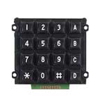
The user interface includes a keypad containing 16 buttons, arranged as shown on the right.
Real Time Mode
Our Automated Xylophone defaults to real time mode. In real time mode, the first two rows of buttons (1-3, A, 4-6 and B) are used to determine xylophone note. As soon as a button is depressed, it will immediately trigger a solenoid to play the chosen note. Tp return to real time mode after entering edit mode or playback mode, you reset the PIC.
Edit Mode
To enter edit mode, you hit button *. Edit mode allows you to store about 250 notes, including rests, per block. Once you first enter edit mode, you must select which block you would like to store your collection of notes. To increase the block number, use button C. Button 9 will decrease the block number. Once you have selected your block, you hit the enter button, button D. Now, you are ready to begin programming notes.
As in real time mode, the first two rows of buttons still determine which note to program. Buttons 7 and 8 will adjust the note duration to longer and shorter respectively. Buttons 9 and C will adjust the which sequential number is being programmed. As with determining block number, button C increases the note number and button 9 will decrease the note number. Rests can be programmed using button #. To enter and store a note, you use the enter button, button #. Once you have finished entering the string of notes you would like to store, you hit button 0. Hitting this button will bring you to playback mode.
Playback Mode
The user enters playback mode after going through edit mode. You can enter playback mode without having actually programmed anything in edit mode by simply pressing the 0 button after having entered edit mode. Once you are in playback mode, you select which block you would like to play similar to how you programmed which box you would like to edit. Button C will increase the block number, button 9 will decrease the block number. To select the block and play the stored notes, you hit the # button.
Parts List
Mechanical Components
- 8 Jameco 262262 (Pull-type) 12V Solenoids for more information look here
- Wood used for housing
- Aluminum and foam core were used to position the solenoids at the appropriate height
Electronic Components
- 1 PIC Microcontroller
- 1 Button Pad 4x4 Breakout PCB found here
- 1 Button Pad 4x4 Covering found here
- 1 LCD Screen
- 1 24FC1025 EEPROM whose data sheet can be found here
- 8 Jameco Shinmei 2A 5V DPDT Relay RSB-5-S
- 8 Small Signal Diodes found here
- 6 1k resistors
- 4 NPN transistors
- 1 1k potentiometer
The Xylophone
The xylophone that we selected can be found and purchased here.
Mechanical Design
We decided to incorporate solenoids into our design as a method to strike the xylophone keys. Solenoids are on-off actuators consisting of a plunger moving in an electromagnetic field. Since we decided to use pull-type solenoids, when the solenoids are powered, the plunger is "pulled" or attracted to the powered coils. For more information on solenoids, check out Actuators Available in the Mechatronics Lab.
Mechanical Interface
Our mechanical design was fairly simple and straightforward. We needed to determine the optimal way for the solenoids to hit the xylophone keys, and a way to support them in that position. Initially, we found it to be most intuitive for the solenoids to strike downward onto the keys. However, that design would require us to keep the solenoids powered during rest. Therefore, we choose to have our solenoids strike from below the xylophone which allows us to keep them powered off while inactive.
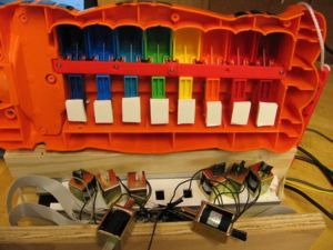
One feature of our mechanical design is that with the xylophone chosen as the bars are hit, the piano keys depress. This design creates the appearance of a phantom piano player.
Solenoid Positioning
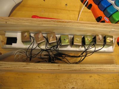
To improve aesthetics and support the xylophone at the proper height, we created a wooden housing for the solenoids. Within the housing, our solenoids rest on an aluminum beam which hold them at the appropriate height. On our aluminum beam, we have a ladder-like structure made of foam core to hold the solenoids in place.
Foam core was also placed underneath each bar of the xylophone, as is shown. The purpose of this addition was to allow a greater acceptable surface for the solenoid to interact with the xylophone. Tape was also placed around the piston of the solenoids, as can be seen in the photos. This technique was a temporary solution to prevent the solenoids from banging on the aluminum beam and keep them at an operable height once powered at 12 V. The xylophone is placed on top of the wooden housing with the bars properly aligned with the solenoids.
Electrical Design
Circuit Diagram
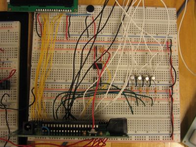
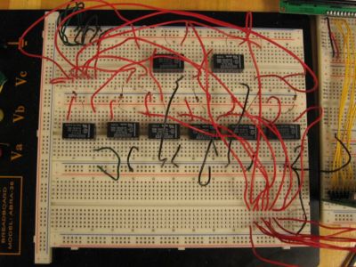
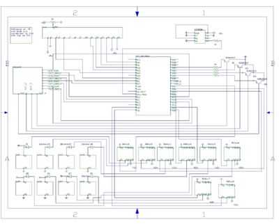
Creating the Automated Xylophone did require some intricate circuitry, as can be seen in the picture of our circuit and our circuit diagram. The most complicated aspects included powering our solenoids using an external power supply and relays, connecting the LCD screen to our PIC and using an EEPROM to store our song information in edit mode. More detailed descriptions of these steps can be found below.
Powering the Solenoids
Since the solenoids need to operate at full voltage and required a lot of current, we were unable to power them using the PIC. Instead, we worked with an external power supply and relays. Check out our circuit diagram to get a better idea of how we incorporated the relays into our circuit.
Connecting the LCD
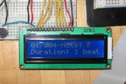
The LCD screen allows the user to monitor his progress in programming for edit mode. To learn more about incorporating an LCD screen, check here
Using an EEPROM
For our Automated Xylophone, an EEPROM is used to store all of the note information during edit and playback mode. More information on connecting an EEPROM to a PIC can be found here and here.
Code
Within our code, we used multiplexing to interface the PIC with the keypad. To learn more about our technique for doing so, check out our code below. You can also learn more about multiplexing here.
Commented Main Code File
//Brandon Robins, Neil Tiwari, Jennifer Yong
//Team 24: Automated Xylophone Final Code

#include <18f4520.h>
#fuses HS,NOLVP,NOWDT,NOPROTECT
#use delay(clock=40000000)
#use i2c(MASTER, FAST, SCL=PIN_C3, SDA=PIN_C4, FORCE_HW)    // use hardware i2c controller
#define EEPROM_WR 0xA0                // Define initial EEPROM write address block (See EEPROM data sheet)
#define EEPROM_RD 0xA1                // Define initial EEPROM read address block (See EEPROM data sheet)
#define LED_GND1  PIN_C7              // Define LED GND pins
#define LED_GND2  PIN_E1
#define LED_GND3  PIN_E2
#define LED_GND4  PIN_C6
/*#define SWT_GND1  PIN_C0       // Already defined in key.c as col0-3
#define SWT_GND2  PIN_C1
#define SWT_GND3  PIN_C2
#define SWT_GND4  PIN_C5
#define SWITCH1  PIN_B1          // Already defined in key.c as row0-3
#define SWITCH2  PIN_B2
#define SWITCH3  PIN_B3
#define SWITCH4  PIN_B4 */
#define SOL8  PIN_D0            // Define Solenoid Output Pins
#define SOL7  PIN_D1
#define SOL6  PIN_D2
#define SOL5  PIN_D3
#define SOL4  PIN_D4
#define SOL3  PIN_D5
#define SOL2  PIN_D6
#define SOL1  PIN_D7

//Include LCD and keypad multiplexing code files
#include "flex_lcd.c"
#include "key.c"


// Define Variables
int block = 1, sel_note, i, j = 1, note_lengths[4] = {1 2 4 8};
int16 address, dis_address = 1, duration, temp_duration, temp_note, value;
//char notes[] = {"R" "C" "C" "D" "D" "E" "F" "F" "G" "G" "A" "A" "B"}; // for use with 12 keys and 12 solenoids
char notes[] = {"R" "C" "D" "E" "F" "G" "A" "B" "C"};
//char note_quality[] = {"E" " " "#" " " "#" " " " " "#" " " "#" " " "#" " "}; // for use with 12 keys and 12 solenoids
char note_quality[] = {"E" " " " " " " " " " " " " " " "8" " " " " " " " "};

void write_eeprom(int16 address, int16 data) //Writing to the EEPROM function
{
   i2c_start();
   i2c_write(EEPROM_WR);
   i2c_write(address>>8);
   i2c_write(address);
   i2c_write(data);
   i2c_stop();
   delay_ms(5);   //Delay time needed in order to allow EEPROM to write data from buffer to memory sector
}

int16 read_eeprom(int16 address) // Reading from the EEPROM function
{
   i2c_start();
   i2c_write(EEPROM_WR);
   i2c_write(address>>8);
   i2c_write(address);
   i2c_start();
   i2c_write(EEPROM_RD);
   value = i2c_read(0);
   i2c_stop();
   return(value);
}


// Edit Address Block allows you to change which address block is being written too
int edit_block_select()
{
char keypress;
kbd_init();
printf(lcd_putc,"\fEdit Address\n  Block # %02d",block);
while(1){
   keypress = kbd_getc();

      if ((keypress == 'C') && (block < 10)){
      block++;
      printf(lcd_putc,"\fEdit Address\n  Block # %02d",block);
      }
      if ((keypress == '9') && (block > 1)){
      block--;
      printf(lcd_putc,"\fEdit Address\n  Block # %02d",block);
      }
      if (keypress == 'D'){
      return block;
      break;
      }
      if (keypress == '*'){
      break;
      }
   }
}


//This part of the code lets the user select keys for use in edit mode
void key_select()
{
dis_address = 1;
   if (block == 1) address = 0;
   if (block == 2) address = 500;
   if (block == 3) address = 1000;
   if (block == 4) address = 1500;
   if (block == 5) address = 2000;
   if (block == 6) address = 2500;
   if (block == 7) address = 3000;
   if (block == 8) address = 3500;
   if (block == 9) address = 4000;
   if (block == 10) address = 4500;
sel_note = read_eeprom(address);
duration = read_eeprom(address+1);
if (sel_note > 12) sel_note = 1;
//if (duration > 8) duration = 2;
duration = note_lengths[1];
kbd_init();
printf(lcd_putc,"\f%02d/%03lu-Note: %c%c \nDuration: %1lu beat",block,dis_address,notes[sel_note],note_quality[sel_note],duration);
   while (1) {

   keypress = kbd_getc(); //Get keypad input from key.c

      if (keypress == '1') {
         sel_note = 1;
         printf(lcd_putc,"\f%02d/%03lu-Note: %c%c \nDuration: %1lu beat",block,dis_address,notes[sel_note],note_quality[sel_note],duration);
      }
      if (keypress == '2') {
         sel_note = 2;
         printf(lcd_putc,"\f%02d/%03lu-Note: %c%c \nDuration: %1lu beat",block,dis_address,notes[sel_note],note_quality[sel_note],duration);
      }
      if (keypress == '3') {
         sel_note = 3;
         printf(lcd_putc,"\f%02d/%03lu-Note: %c%c \nDuration: %1lu beat",block,dis_address,notes[sel_note],note_quality[sel_note],duration);
      }
      if (keypress == 'A') {
         sel_note = 4;
         printf(lcd_putc,"\f%02d/%03lu-Note: %c%c \nDuration: %1lu beat",block,dis_address,notes[sel_note],note_quality[sel_note],duration);
      }
      if (keypress == '4') {
         sel_note = 5;
         printf(lcd_putc,"\f%02d/%03lu-Note: %c%c \nDuration: %1lu beat",block,dis_address,notes[sel_note],note_quality[sel_note],duration);
      }
      if (keypress == '5') {
         sel_note = 6;
         printf(lcd_putc,"\f%02d/%03lu-Note: %c%c \nDuration: %1lu beat",block,dis_address,notes[sel_note],note_quality[sel_note],duration);
      }
      if (keypress == '6') {
         sel_note = 7;
         printf(lcd_putc,"\f%02d/%03lu-Note: %c%c \nDuration: %1lu beat",block,dis_address,notes[sel_note],note_quality[sel_note],duration);
      }
      if (keypress == 'B') {
         sel_note = 8;
         printf(lcd_putc,"\f%02d/%03lu-Note: %c%c \nDuration: %1lu beat",block,dis_address,notes[sel_note],note_quality[sel_note],duration);
      }
      if ((keypress == '7') && (j < 3)) {
         //sel_note = 9;
         j++;
         duration = note_lengths[j];
         printf(lcd_putc,"\f%02d/%03lu-Note: %c%c \nDuration: %1lu beat",block,dis_address,notes[sel_note],note_quality[sel_note],duration);
      }
      if ((keypress == '8') && (j > 0)) {
         //sel_note = 10;
         j--;
         duration = note_lengths[j];
         printf(lcd_putc,"\f%02d/%03lu-Note: %c%c \nDuration: %1lu beat",block,dis_address,notes[sel_note],note_quality[sel_note],duration);
      }
      if ((keypress == 'C') && (dis_address < 250)) {
         address+=2;
         dis_address++;
         printf(lcd_putc,"\f%02d/%03lu-Note: %c%c \nDuration: %1lu beat",block,dis_address,notes[sel_note],note_quality[sel_note],duration);
      }
      if ((keypress == '9') && (dis_address > 1)) {
         address-=2;
         dis_address--;
         printf(lcd_putc,"\f%02d/%03lu-Note: %c%c \nDuration: %1lu beat",block,dis_address,notes[sel_note],note_quality[sel_note],duration);
      }
      if (keypress == '*') {
         //real_time_mode();
      }
      if (keypress == '0') {
         break;
      }
      if (keypress == '#') {
         sel_note = 0;
         printf(lcd_putc,"\f%02d/%03lu-Note: %c%c \nDuration: %1lu beat",block,dis_address,notes[sel_note],note_quality[sel_note],duration);
      }

      // The D key acts like the Enter key. In this case this allows for writing to the EEPROM.
      if (keypress == 'D') {
         write_eeprom(address,sel_note);
         address++;
         write_eeprom(address,duration);
         address++;
         dis_address++;
         temp_note = read_eeprom(address);
         temp_duration = read_eeprom(address+1);
            if (temp_note > 12) sel_note = 1;
            else sel_note = temp_note;

            if (temp_duration > 8) duration = 2;
            else duration = temp_duration;
         printf(lcd_putc,"\f%02d/%03lu-Note: %c%c \nDuration: %1lu beat",block,dis_address,notes[sel_note],note_quality[sel_note],duration);
      }
   }
}

//In Playback mode user can select which address block to play. The xylophone then plays this address block back.
int playback_block_select()
{
char keypress;
kbd_init();
printf(lcd_putc,"\fPlay Address\n  Block # %02d",block);
   while(1){
      keypress = kbd_getc();

      if ((keypress == 'C') && (block < 10)){
      block++;
      printf(lcd_putc,"\fPlay Address\n  Block # %02d",block);
      }

      if ((keypress == '9') && (block > 1)){
      block--;
      printf(lcd_putc,"\fPlay Address\n  Block # %02d",block);
      }

      if (keypress == '#'){
      break;
      }
      if (keypress == '*'){
      return block;
      break;
      }
   }
}

void playback_mode()
{
   playback_block_select();
   dis_address = 1;
   if (block == 1) address = 0;
   if (block == 2) address = 500;
   if (block == 3) address = 1000;
   if (block == 4) address = 1500;
   if (block == 5) address = 2000;
   if (block == 6) address = 2500;
   if (block == 7) address = 3000;
   if (block == 8) address = 3500;
   if (block == 9) address = 4000;
   if (block == 10) address = 4500;

      for (i=0; i<250; i++){
           value = read_eeprom(address); // Send data from analog input to write function
           printf(lcd_putc,"\fAddress: %03lu\nNote: %c%c",dis_address,notes[value],note_quality[value]);
           delay_ms(250);
           if (value == 1){
              output_high(SOL1);            //This section outputs the lows and highs to the solenoids in order to hit the keys
              delay_ms(100);
              output_low(SOL1);
           }
           if (value == 2){
              output_high(SOL2);
              delay_ms(100);
              output_low(SOL2);
           }
           if (value == 3){
              output_high(SOL3);
              delay_ms(100);
              output_low(SOL3);
           }
           if (value == 4){
              output_high(SOL4);
              delay_ms(100);
              output_low(SOL4);
           }
           if (value == 5){
              output_high(SOL5);
              delay_ms(100);
              output_low(SOL5);
           }
           if (value == 6){
              output_high(SOL6);
              delay_ms(100);
              output_low(SOL6);
           }
           if (value == 7){
              output_high(SOL7);
              delay_ms(100);
              output_low(SOL7);
           }
           if (value == 8){
              output_high(SOL8);
              delay_ms(100);
              output_low(SOL8);
           }
           address+=2;
           dis_address++;
      }
}

//In real time mode the user presses a key and the solenoids are activated to hit the keys
void real_time_mode()
{
kbd_init();
lcd_putc("\fReal Time Mode\n");
   while (1) {
   keypress = kbd_getc();
           if (keypress == '1'){
              output_high(SOL1);
              delay_ms(100);
              output_low(SOL1);
           }
           if (keypress == '2'){
              output_high(SOL2);
              delay_ms(100);
              output_low(SOL2);
           }
           if (keypress == '3'){
              output_high(SOL3);
              delay_ms(100);
              output_low(SOL3);
           }
           if (keypress == 'A'){
              output_high(SOL4);
              delay_ms(100);
              output_low(SOL4);
           }
           if (keypress == '4'){
              output_high(SOL5);
              delay_ms(100);
              output_low(SOL5);
           }
           if (keypress == '5'){
              output_high(SOL6);
              delay_ms(100);
              output_low(SOL6);
           }
           if (keypress == '6'){
              output_high(SOL7);
              delay_ms(100);
              output_low(SOL7);
           }
           if (keypress == 'B'){
              output_high(SOL8);
              delay_ms(100);
              output_low(SOL8);
           }
           if (keypress == '*'){
               edit_block_select();
               key_select();
           }
           if (keypress == '0'){
               playback_mode();
           }
   }
}

//Where the code starts
void main()
{
   lcd_init();  // Always call this first.
   lcd_putc("\fHello There...\n");
   kbd_init();
   real_time_mode();
}
Commented LED Code
// flex_lcd.c


#define LCD_DB4   PIN_A3
#define LCD_DB5   PIN_A2
#define LCD_DB6   PIN_A1
#define LCD_DB7   PIN_A0

#define LCD_RS    PIN_E0
#define LCD_RW    PIN_A5
#define LCD_E     PIN_A4


#define USE_LCD_RW   1

//========================================

#define lcd_type 2        // 0=5x7, 1=5x10, 2=2 lines
#define lcd_line_two 0x40 // LCD RAM address for the 2nd line


int8 const LCD_INIT_STRING[4] =
{
 0x20 | (lcd_type << 2), // Func set: 4-bit, 2 lines, 5x8 dots
 0xc,                    // Display on
 1,                      // Clear display
 6                       // Increment cursor
 };


//-------------------------------------
void lcd_send_nibble(int8 nibble)
{
// Note:  !! converts an integer expression
// to a boolean (1 or 0).
 output_bit(LCD_DB4, !!(nibble & 1));
 output_bit(LCD_DB5, !!(nibble & 2));
 output_bit(LCD_DB6, !!(nibble & 4));
 output_bit(LCD_DB7, !!(nibble & 8));

 delay_cycles(1);
 output_high(LCD_E);
 delay_us(2);
 output_low(LCD_E);
}

//-----------------------------------
// This sub-routine is only called by lcd_read_byte().
// It's not a stand-alone routine.  For example, the
// R/W signal is set high by lcd_read_byte() before
// this routine is called.

#ifdef USE_LCD_RW
int8 lcd_read_nibble(void)
{
int8 retval;
// Create bit variables so that we can easily set
// individual bits in the retval variable.
#bit retval_0 = retval.0
#bit retval_1 = retval.1
#bit retval_2 = retval.2
#bit retval_3 = retval.3

retval = 0;

output_high(LCD_E);
delay_cycles(1);

retval_0 = input(LCD_DB4);
retval_1 = input(LCD_DB5);
retval_2 = input(LCD_DB6);
retval_3 = input(LCD_DB7);

output_low(LCD_E);

return(retval);
}
#endif

//---------------------------------------
// Read a byte from the LCD and return it.

#ifdef USE_LCD_RW
int8 lcd_read_byte(void)
{
int8 low;
int8 high;

output_high(LCD_RW);
delay_cycles(1);

high = lcd_read_nibble();

low = lcd_read_nibble();

return( (high<<4) | low);
}
#endif

//----------------------------------------
// Send a byte to the LCD.
void lcd_send_byte(int8 address, int8 n)
{
output_low(LCD_RS);

#ifdef USE_LCD_RW
while(bit_test(lcd_read_byte(),7)) ;
#else
delay_us(60);
#endif

if(address)
   output_high(LCD_RS);
else
   output_low(LCD_RS);

 delay_cycles(1);

#ifdef USE_LCD_RW
output_low(LCD_RW);
delay_cycles(1);
#endif

output_low(LCD_E);

lcd_send_nibble(n >> 4);
lcd_send_nibble(n & 0xf);
}

//----------------------------
void lcd_init(void)
{
int8 i;

output_low(LCD_RS);

#ifdef USE_LCD_RW
output_low(LCD_RW);
#endif

output_low(LCD_E);

delay_ms(15);

for(i=0 ;i < 3; i++)
   {
    lcd_send_nibble(0x03);
    delay_ms(5);
   }

lcd_send_nibble(0x02);

for(i=0; i < sizeof(LCD_INIT_STRING); i++)
   {
    lcd_send_byte(0, LCD_INIT_STRING[i]);

    // If the R/W signal is not used, then
    // the busy bit can't be polled.  One of
    // the init commands takes longer than
    // the hard-coded delay of 60 us, so in
    // that case, lets just do a 5 ms delay
    // after all four of them.
    #ifndef USE_LCD_RW
    delay_ms(5);
    #endif
   }

}

//----------------------------

void lcd_gotoxy(int8 x, int8 y)
{
int8 address;

if(y != 1)
   address = lcd_line_two;
else
   address=0;

address += x-1;
lcd_send_byte(0, 0x80 | address);
}

//-----------------------------
void lcd_putc(char c)
{
 switch(c)
   {
    case '\f':
      lcd_send_byte(0,1);
      delay_ms(2);
      break;

    case '\n':
       lcd_gotoxy(1,2);
       break;

    case '\b':
       lcd_send_byte(0,0x10);
       break;

    default:
       lcd_send_byte(1,c);
       break;
   }
}

//------------------------------
#ifdef USE_LCD_RW
char lcd_getc(int8 x, int8 y)
{
char value;

lcd_gotoxy(x,y);

// Wait until busy flag is low.
while(bit_test(lcd_read_byte(),7));

output_high(LCD_RS);
value = lcd_read_byte();
output_low(lcd_RS);

return(value);
}
#endif
Commented Keypad Code
//=============================

//Keypad connection:
#define row0 PIN_B1
#define row1 PIN_B2
#define row2 PIN_B3
#define row3 PIN_B4
#define col0 PIN_C0
#define col1 PIN_C1
#define col2 PIN_C2
#define col3 PIN_C5

// Keypad layout:
char const KEYS[4][4] =
{{'A','3','2','1'},
 {'B','6','5','4'},
 {'C','9','8','7'},
 {'D','#','0','*'}};

char keypress;

#define KBD_DEBOUNCE_FACTOR 33 // Set this number to apx n/333 where
// n is the number of times you expect
// to call kbd_getc each second


//initialize keypad
void kbd_init()
{
//set_tris_b(0xF0);
//output_b(0xF0);
port_b_pullups(true);
}


//set all rows to high
short int ALL_ROWS (void)
{
if(input (row0) & input (row1) & input (row2) & input (row3))
   return (0);
else
   return (1);
}

char kbd_getc()
{
static byte kbd_call_count;
static short int kbd_down;
static char last_key;
static byte col;

byte kchar;
byte row;

kchar='\0';

//pulse various columns with high
if(++kbd_call_count>KBD_DEBOUNCE_FACTOR)
  {
   switch (col)
     {
      case 0:
        output_low(col0);
        output_high(col1);
        output_high(col2);
        output_high(col3);
        break;

      case 1:
        output_high(col0);
        output_low(col1);
        output_high(col2);
        output_high(col3);
        break;

      case 2:
        output_high(col0);
        output_high(col1);
        output_low(col2);
        output_high(col3);
        break;

      case 3:
        output_high(col0);
        output_high(col1);
        output_high(col2);
        output_low(col3);
        break;
      }

   if(kbd_down)
     {
      if(!ALL_ROWS())
        {
         kbd_down=false;
         kchar=last_key;
         last_key='\0';
        }
     }
   else
     {
      if(ALL_ROWS())
        {
         if(!input (row0))
            row=0;
         else if(!input (row1))
            row=1;
         else if(!input (row2))
            row=2;
         else if(!input (row3))
            row=3;

         last_key =KEYS[row][col];
         kbd_down = true;
        }
      else
        {
         ++col;
         if(col==4)
            col=0;
        }
     }
   kbd_call_count=0;
  }

//return the detected key
return(kchar);
}
Results and Next Steps
Results
Our Automated Xylophone operated as expected, with full capability in both real time mode, edit mode and playback Mode. We were also able to get excellent sound on our xylophone. A video of our Automated Xylophone playing in real time mode can be found here. A video of our Automated Xylophone playing in playback mode can be found here with vies of the LCD screen during playback mode here.
Next Steps
Given more time, potential next steps include:
- Allowing the user to play multiple notes at the same time or chords
- Allowing the user to hear what notes they are programming while in edit mode
- Allowing the keypad to use wireless connectivity to send information to the xylophone
- Creating an enclosure for the circuitry
- Creating a more permanent housing for the solenoids and xylophone
- Incorporating the RGB LEDs on the Keypad
References
Actuators Available in the Mechatronics Lab
Data logging with an EEPROM
Interfacing to External EEPROM
C Example: Parallel Interfacing with LCDs
Multiplexing
