C Example: Parallel Interfacing with LCDs
Making use of 7 general IO ports on the PIC18F4520 it is possible to easily interface with the popular HD44780 (and compatible chipsets) for easy character output to an LCD. This can be highly useful in either debugging or generating a more complex user interface for a PIC (or other microcontroller)-based device.
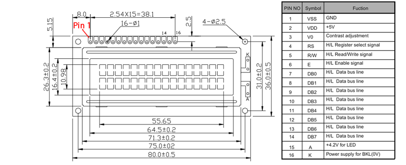
First you will need to locate the appropriate datasheet for the actual LCD you are using. What you will want to look up in there is the arrangement of connectors on the top-left of the display, and their names so that you can appropriately match the right connectors with the correct pins on the microcontroller, and in turn with the correct software identifiers for those connections. An example of one such pin arrangement is below (for a GDM1602K LCD with a KS0066U controller).
Your controller may differ from this one. Occasionally even if you've got the right datasheet these pin numbers can be backwards. If it has a backlight, try powering that up first and ensure that works.
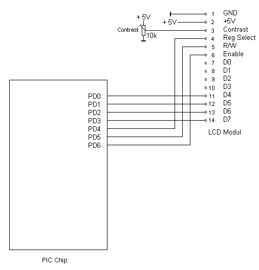
Next, you'll need to wire up the LCD for power, and the connections with the pic. I used a 10K pot for contrast.
You can rearrange which of the LCD pins connect to which on the PIC (including using another port if PORT D is taken on your project), so long as you adjust the source code appropriately.
Below is the code you'll want to include with your project with the above wiring.
// flex_lcd.c

// These pins are for the Microchip PicDem2-Plus board,
// which is what I used to test the driver.  Change these
// pins to fit your own board.

#define LCD_DB4   PIN_D0
#define LCD_DB5   PIN_D1
#define LCD_DB6   PIN_D2
#define LCD_DB7   PIN_D3

#define LCD_RS    PIN_D4
#define LCD_RW    PIN_D5
#define LCD_E     PIN_D6

// If you only want a 6-pin interface to your LCD, then
// connect the R/W pin on the LCD to ground, and comment
// out the following line.

#define USE_LCD_RW   1

//========================================

#define lcd_type 2        // 0=5x7, 1=5x10, 2=2 lines
#define lcd_line_two 0x40 // LCD RAM address for the 2nd line


int8 const LCD_INIT_STRING[4] =
{
 0x20 | (lcd_type << 2), // Func set: 4-bit, 2 lines, 5x8 dots
 0xc,                    // Display on
 1,                      // Clear display
 6                       // Increment cursor
 };


//-------------------------------------
void lcd_send_nibble(int8 nibble)
{
// Note:  !! converts an integer expression
// to a boolean (1 or 0).
 output_bit(LCD_DB4, !!(nibble & 1));
 output_bit(LCD_DB5, !!(nibble & 2));
 output_bit(LCD_DB6, !!(nibble & 4));
 output_bit(LCD_DB7, !!(nibble & 8));

 delay_cycles(1);
 output_high(LCD_E);
 delay_us(2);
 output_low(LCD_E);
}

//-----------------------------------
// This sub-routine is only called by lcd_read_byte().
// It's not a stand-alone routine.  For example, the
// R/W signal is set high by lcd_read_byte() before
// this routine is called.

#ifdef USE_LCD_RW
int8 lcd_read_nibble(void)
{
int8 retval;
// Create bit variables so that we can easily set
// individual bits in the retval variable.
#bit retval_0 = retval.0
#bit retval_1 = retval.1
#bit retval_2 = retval.2
#bit retval_3 = retval.3

retval = 0;

output_high(LCD_E);
delay_cycles(1);

retval_0 = input(LCD_DB4);
retval_1 = input(LCD_DB5);
retval_2 = input(LCD_DB6);
retval_3 = input(LCD_DB7);

output_low(LCD_E);

return(retval);
}
#endif

//---------------------------------------
// Read a byte from the LCD and return it.

#ifdef USE_LCD_RW
int8 lcd_read_byte(void)
{
int8 low;
int8 high;

output_high(LCD_RW);
delay_cycles(1);

high = lcd_read_nibble();

low = lcd_read_nibble();

return( (high<<4) | low);
}
#endif

//----------------------------------------
// Send a byte to the LCD.
void lcd_send_byte(int8 address, int8 n)
{
output_low(LCD_RS);

#ifdef USE_LCD_RW
while(bit_test(lcd_read_byte(),7)) ;
#else
delay_us(60);
#endif

if(address)
   output_high(LCD_RS);
else
   output_low(LCD_RS);

 delay_cycles(1);

#ifdef USE_LCD_RW
output_low(LCD_RW);
delay_cycles(1);
#endif

output_low(LCD_E);

lcd_send_nibble(n >> 4);
lcd_send_nibble(n & 0xf);
}

//----------------------------
void lcd_init(void)
{
int8 i;

output_low(LCD_RS);

#ifdef USE_LCD_RW
output_low(LCD_RW);
#endif

output_low(LCD_E);

delay_ms(15);

for(i=0 ;i < 3; i++)
   {
    lcd_send_nibble(0x03);
    delay_ms(5);
   }

lcd_send_nibble(0x02);

for(i=0; i < sizeof(LCD_INIT_STRING); i++)
   {
    lcd_send_byte(0, LCD_INIT_STRING[i]);

    // If the R/W signal is not used, then
    // the busy bit can't be polled.  One of
    // the init commands takes longer than
    // the hard-coded delay of 60 us, so in
    // that case, lets just do a 5 ms delay
    // after all four of them.
    #ifndef USE_LCD_RW
    delay_ms(5);
    #endif
   }

}

//----------------------------

void lcd_gotoxy(int8 x, int8 y)
{
int8 address;

if(y != 1)
   address = lcd_line_two;
else
   address=0;

address += x-1;
lcd_send_byte(0, 0x80 | address);
}

//-----------------------------
void lcd_putc(char c)
{
 switch(c)
   {
    case '\f':
      lcd_send_byte(0,1);
      delay_ms(2);
      break;

    case '\n':
       lcd_gotoxy(1,2);
       break;

    case '\b':
       lcd_send_byte(0,0x10);
       break;

    default:
       lcd_send_byte(1,c);
       break;
   }
}

//------------------------------
#ifdef USE_LCD_RW
char lcd_getc(int8 x, int8 y)
{
char value;

lcd_gotoxy(x,y);

// Wait until busy flag is low.
while(bit_test(lcd_read_byte(),7));

output_high(LCD_RS);
value = lcd_read_byte();
output_low(lcd_RS);

return(value);
}
#endif
Save this as flex_lcd.c in your project's directory.
If you want different ports, change the following section in the above code
#define LCD_DB4   PIN_D0
#define LCD_DB5   PIN_D1
#define LCD_DB6   PIN_D2
#define LCD_DB7   PIN_D3

#define LCD_RS    PIN_D4
#define LCD_RW    PIN_D5
#define LCD_E     PIN_D6
RS may be referred to as Register select, or select. E may be referred to as enable, on your datasheet.
Example code to try out your connections is below:
#include <18F4520.h>
#fuses HS,NOWDT,PUT,NOLVP
#use delay(clock=20000000)
#include "flex_lcd.c"

//==========================
void main()
{
lcd_init();  // Always call this first.

lcd_putc("\fHello World\n");
lcd_putc("Line Number 2");

while(1);
}
Instead of using lcd_putc, one can also use the following if formatted printing is desired:
printf(lcd_putc,"\fMyVar:%3.2f",MyVar);
LCD connections diagram was derived from Peter Fleury's excellent guide on using these types of LCDs with AVR microcontrollers.
The PIC CCS code above is almost entirely derived from this article on the CCS forums. Special thanks to PCM Programmer.

