Data logging with an EEPROM
Original Assignment
Your task is to use the PIC to log data from an analog input on an EEPROM, and after the data collection is over, to send the data back from the EEPROM to a PC running matlab. Use an interrupt service routine to read an analog input and write the value to an external EEPROM using I2C. After reading in a fixed number of samples, perhaps 1,000 or 10,000, the program should send the data back to a matlab program via an RS-232 link. The logged data should then be plotted by matlab.
You should decrease the sample time until the ISR does not successfully complete. What is the fastest rate at which an analog input can be read and stored to the external EEPROM? Try this for an analog input configured for both 8-bit (1 byte of data stored on the EEPROM) and 10-bit (2 bytes of data stored on the EEPROM). How much data can you store on the EEPROM?
As an alternative, you can avoid the use of an ISR and simply read and store the data as fast as you can in a loop.
As a test input, use a triangle wave signal from the function generator between 1 and 4 V, and plot the data in matlab.
See Interfacing to External EEPROM, PIC RS232, and Serial communication with Matlab.
Overview
An external EEPROM is useful when trying to store data. In addition to storing much more data than is available on the 18F4520 PIC, an EEPROM stores the data even when power is removed and can then be collected at a later time. Storing large amounts of data over time is especially beneficial once communication can be made between the PIC and Matlab. Using the serial function in Matlab, the data can be obtained and then analyzed.
In this project, we used the PIC to log data from an analog input onto an EEPROM and then later sent the data back from the EEPROM to Matlab to plot. For our lab, we worked with a 24FC1025 EEPROM whose data sheet can be found here. Additionally, we established serial port connection between the PIC microcontroller and Matlab using the RS232. Our project also made use of two buttons. The first button tells the PIC to begin collecting data points from the analog input and storing the data onto the EEPROM. The second button tells the PIC to send the data from the EEPROM to Matlab.
Circuit
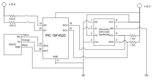
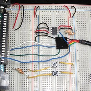
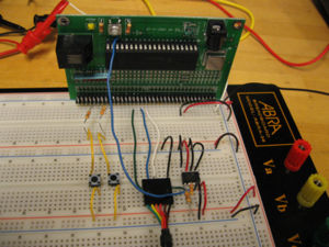
To the right is a circuit diagram for interfacing a 24FC1025 EEPROM to the 18F4520 PIC. Below the diagram are photos of the circuit layout.
For more details regarding pin assignments for the EEPROM, see here.
To operate the EEPROM, PIN1 and PIN2, A0 and A1 are set to ground. PIN3, A2 is connected to high for normal operation. PIN4, Vss is used to ground the chip. PIN5, SDA is the serial data line and is connected to RC4 (PIN23) on the PIC. PIN6, SCL is the serial clock line which is connected to RC3 (PIN18) on the PIC. PIN7, WP is the write protect line. For our purposes, we set PIN7 to ground to disable this function and allow us to rewrite our data onto the EEPROM. PIN8, Vcc is connected to high to power the chip.
In order to connect our PIC to Matlab, we use the RS232. As mentioned here, we connect the black wire to ground, the orange wire to pin 26, RC7 and the yellow wire to pin 25, RC6.
Additionally, we used two buttons connected to digital inputs on the PIC which dictate when to collect and store data and when to send the data to Matlab.
Code
This project consists of two sets of code: code that is downloaded to the PIC to collect and store data to and send data from the EEPROM , and code that is used by Matlab to collect and plot the data. Within our code, we use a delay time of 5 msec since this is the time required to write the data to the EEPROM. We collect 1000 data points in our code. However, the maximum number of data points is 128,000 assuming each data point is a byte. The EEPROM is capable of storing 1024K bits or 128K bytes.
PIC Code
/*
  superawesomeeepromcode.c Brandon Robins, Neil Tiwari, Jenny Yong 2009-2-11
  Upon pressing button 1, take 1000 data values from AN0 and save to EEPROM
  Upon pressing button 2, wait for Matlab response, then output all data points from EEPROM
*/

#include <18f4520.h>
#fuses HS,NOLVP,NOWDT,NOPROTECT
#use delay(clock=40000000)
#use i2c(MASTER, FAST, SCL=PIN_C3, SDA=PIN_C4, FORCE_HW)    // use hardware i2c controller
#use rs232(baud=9600, UART1)          // Set up PIC UART on RC6 (tx) and RC7 (rx)
#define EEPROM_WR 0xA0                // Define initial EEPROM write address block (See EEPROM data sheet)
#define EEPROM_RD 0xA1                // Define initial EEPROM read address block (See EEPROM data sheet)

int button1, button2, data_rx = 48;   // Initialize variables
int16 i, temp, value, address = 0, data;

void seq_write(int16 address, int16 data)//Writing to the EEPROM function
{
  i2c_start();
  i2c_write(EEPROM_WR);
  i2c_write(address>>8);
  i2c_write(address);
  i2c_write(data);
  i2c_stop();
  delay_ms(5);//Delay time needed in order to allow EEPROM to write data from buffer to memory sector
}

int16 seq_read(int16 address)// Reading from the EEPROM function
{
  i2c_start();
  i2c_write(EEPROM_WR);
  i2c_write(address>>8);
  i2c_write(address);
  i2c_start();
  i2c_write(EEPROM_RD);
  value = i2c_read(0);
  i2c_stop();
  return(value);
}

void main() //Main Function
{
setup_adc_ports(AN0); //Setup Analog Inputs
set_adc_channel(0);
setup_adc(ADC_CLOCK_INTERNAL);

  while (TRUE)
  {
    button1 = input(PIN_D0); // Button one is pressed when the user wants to write to the EEPROM
    button2 = input(PIN_D1); // Button two is pressed when the user wants to read from the EEPROM and send the data to Matlab

     if (button1 == 1) {
     output_high(PIN_D0);//LED is turned on to show that writing to the EEPROM has begun
     address = 0x00;
        for (i=0; i<1000; i++){
        data = read_adc();//Read in data from analog input (In this case it was attached to a function generator)
        seq_write(address, data); // Send data from analog input to write function
        address++; // Increment up the address location on the EEPROM for the next time it writes something
        }
     output_low(PIN_D0); // LED is turned off to show that writing to the EEPROM is complete
    }

     if (button2 == 1) {
     address = 0x00; // start at the first address location
        while (data_rx == 48) {
           output_high(PIN_D1);
           if (kbhit()){
           data_rx = fgetc();
           temp = seq_read(address); //read data from adress location
           printf("%lu \r",temp); // sends data to serial port
           address++; // increment up the address so it can read from the next data sector
           }

           button1 = input(PIN_D0);
           if (button1 == 1){
           output_low(PIN_D1);
           data_rx = 48;  // 48 is the ASCII Code for integer '0'
           delay_ms(500);
           break;// Basically break from this loop if user presses the first button
           }
        }
     data_rx = 48;  // 48 is the ASCII Code for integer '0'
     }
  }
}
Matlab Code
%Brandon Robins, Neil Tiwari and Jenny Yong
%serialcom.m
%Construct serial port object, then send confirmation for EEPROM data

%deletes any serial port objects that exist in memory
delete(instrfind)
%Define serial COM Port
s1 = serial('COM8');
%Open the com port
fopen(s1);

set(s1,'Terminator','CR');

%Length of data points to be retrieved from EEPROM
final = 1000;

%For loop for retrieving data from the EEPROM
for ii = 1:final
   if ii ~= final
       %Send EEPROM "0" to signal that a data point should be sent
       fprintf(s1,'%s','0')
       %Get data point from eeprom
       x(ii) = fscanf(s1,'%g');
   else
       %At the very last data point send EEPROM "1" to terminate the
       %sending process
       fprintf(s1,'%s','1')
       % Get final data point from EEPROM
       x(ii) = fscanf(s1,'%g');
   end
end

%Close serial port
fclose(s1);
%Delete serial port object
delete(s1);
%Plot retrieved data
plot(x)
Example Output
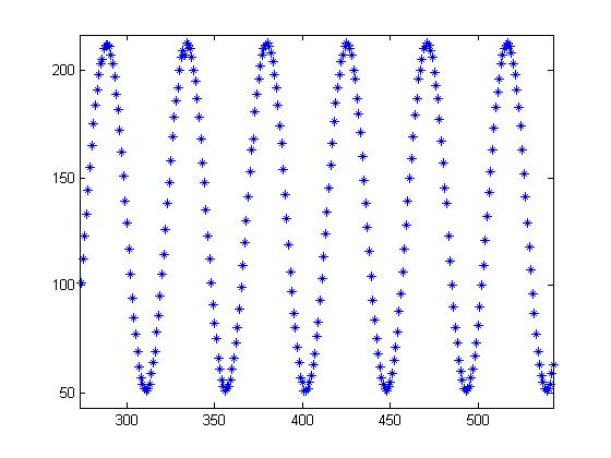
We input a sine wave from the function generator into the analog input of the PIC and sampled the voltages from the sine wave and saved them to the EEPROM. Matlab was then able to retreive the values from the EEPROM and plot the data. The key limitation of this example is the sampling rate of the code. Since it take 5 ms to write each data point to the EEPROM, the maximum sampling rate is therefore 200 Hz.


