Difference between revisions of "Ultrasonic ranging"
Ben Tollberg (talk | contribs) (→Code) |
|||
| (14 intermediate revisions by 3 users not shown) | |||
| Line 1: | Line 1: | ||
== Original Assignment == |
|||
In this project you will demonstrate that you can measure distances using an ultrasonic transmitter and receiver, at distances up to a few meters. While you could build from components (see, for example, [http://www.micro-examples.com/public/microex-navig/doc/090-ultrasonic-ranger.html this website]), in this project you will use [https://www.parallax.com/Store/Sensors/ObjectDetection/tabid/176/CategoryID/51/List/0/Level/a/ProductID/92/Default.aspx?SortField=ProductName%2cProductName this pre-packaged PING))) ultrasonic sensor]. Your results can be displayed on an LCD screen (see, e.g., [[C Example: Serial LCD]] or [[C Example: Parallel Interfacing with LCDs]]) or on a PC using the USB/RS-232 cable (see [[PIC RS232]]). |
|||
== Overview == |
== Overview == |
||
[[Image:Ultrasonic_Ranging.JPG|right|thumb|400px|]] |
[[Image:Ultrasonic_Ranging.JPG|right|thumb|400px|]] |
||
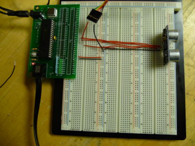
The Ping Ultrasonic Distance Sensor by Parallax has three pins. These pins are +5V, I/O, and Ground. In order to activate the sensor, a 5 microsecond 5V signal must be sent to the I/O pin. The sensor then waits 750 microseconds before sending an ultrasonic wave. The sensor sets the I/O pin to high (+5V). When the sensor receives the reflected ultrasonic wave, it sets the I/O pin to low. The time that the I/O pin is high represents twice the distance of the object, as the wave must travel to the object and be reflected back. The sensor is rated for 2cm to 3m, though it will measure distances as far as 3.47m. After the sensor has received a signal there is a 200 microsecond refractory period. Due to the delay and the refractory period, one must wait 19.455 milliseconds between successive measurements (18.5 milliseconds to measure 3m + 5 microseconds to active the sensor + 750 microsecond delay + 200 microsecond refractory period). Charts diagramming the effects of elevation and angle of the object relative to the sensors can be found in the product documentation ([https://www.parallax.com/Portals/0/Downloads/docs/prod/acc/28015-PING-v1.5.pdf]). |
|||
<br><br><br><br> |
|||
== Circuit == |
== Circuit == |
||
[[Image:Ultrasonic_Ranging_Schematic.jpg|right|thumb|400px|]] |
[[Image:Ultrasonic_Ranging_Schematic.jpg|right|thumb|400px|]] |
||
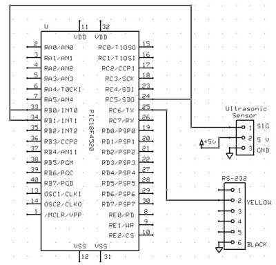
In the circuit, the black wire represents ground. Pin C5 was used as the output pin responsible for activating the sensor. The external triggers RB0 and RB1 were used to identify when the I/O pin of the sensor was set to high and low respectively. Pin C6 is used for RS-232 communication to the PC. In order to setup LCD output, see [[C Example: Parallel Interfacing with LCDs]]. |
|||
<br><br><br><br><br><br><br><br><br><br><br><br><br><br><br><br><br><br> |
|||
== Code == |
== Code == |
||
Setup RS 232 support with appropriate baud rate and UART support. |
|||
#include <18f4520.h> |
#include <18f4520.h> |
||
#fuses HS,NOLVP,NOWDT,NOPROTECT |
#fuses HS,NOLVP,NOWDT,NOPROTECT |
||
#use delay(clock=40000000) |
#use delay(clock=40000000) |
||
#use rs232(baud=19200, UART1) |
#use rs232(baud=19200, UART1) |
||
Global variables for the timer and the distance. |
|||
int16 timer; |
int16 timer; |
||
float distance; |
float distance; |
||
This interrupt will be activated when external trigger RB0 transitions from Low to High. This function will initialize Timer 1 to 0. |
|||
#INT_EXT |
|||
#INT_EXT // designates that this is the routine to call when pin RB0/INTO changes state |
|||
void INT0isr() { |
void INT0isr() { |
||
SET_TIMER1(0); |
SET_TIMER1(0); |
||
} |
} |
||
This interrupt will be activated when external trigger RB1 transitions from High to Low. This function will retrieve the time from Timer 1. It will then calculate the distance of the object. The .0000004 term represents the .8 microsecond increment of Timer 1 divided by 2. Division by 2 is required since the wave must travel twice the distance that is being measured. The speed of sound is estimated as 343 m/s at room temperature. If there is a temperature sensor, the speed of sound can be calculated as follows: <math>Csound=331.5+(.6*TCelsius)</math>. The if statement is used to prevent the detection of the activation signal. |
|||
#INT_EXT1 // designates that this is the routine to call when pin RB1/INT1 changes state |
|||
#INT_EXT1 |
|||
void INT1isr() { |
void INT1isr() { |
||
timer=GET_TIMER1(); |
timer=GET_TIMER1(); |
||
distance=timer*.0000004*343; |
distance=timer*.0000004*343; |
||
//microsecond increments of Timer 1, 2 is to divide the distance by half, 343 |
|||
//is the speed of sound in meters, which can be changed |
|||
if(distance >.01) { |
if(distance >.01) { |
||
printf("%f meters\n",distance); |
printf("%f meters\n",distance); |
||
} |
} |
||
} |
} |
||
void main() { |
void main() { |
||
Enable the interrupts on pin RB0 and RB1 |
|||
enable_interrupts(INT_EXT); |
enable_interrupts(INT_EXT); |
||
enable_interrupts(INT_EXT1); |
enable_interrupts(INT_EXT1); |
||
enable_interrupts(GLOBAL); |
enable_interrupts(GLOBAL); |
||
ext_int_edge(0, L_TO_H); |
ext_int_edge(0, L_TO_H); |
||
ext_int_edge(1, H_TO_L); |
ext_int_edge(1, H_TO_L); |
||
| ⚫ | |||
Initialize Timer 1. Timer 1 will count in .8 microsecond increments. |
|||
setup_timer_1(T1_INTERNAL|T1_DIV_BY_8); |
|||
This loop will continue continuously measure the distance of an object. |
|||
while(true) { |
while(true) { |
||
output_high(PIN_C5); //send signal to Ultrasonic Sensor for 5 microseconds |
|||
A 5 microsecond signal activates the sensor. |
|||
output_high(PIN_C5); |
|||
delay_us(5); |
delay_us(5); |
||
output_low(PIN_C5); |
output_low(PIN_C5); |
||
input(PIN_C5); // set pin to input, since the sensor has one pin for I/O, pin c5 can not be outputting a signal |
|||
The PIC pin must be set to an input to permit the sensor pin to send a signal. |
|||
| ⚫ | |||
input(PIN_C5); |
|||
A delay is added since there is a refractory period for the sensor. This delay can be changed to as low as 19.5 milliseconds. |
|||
| ⚫ | |||
| ⚫ | |||
} |
} |
||
Latest revision as of 02:11, 16 February 2009
Overview
The Ping Ultrasonic Distance Sensor by Parallax has three pins. These pins are +5V, I/O, and Ground. In order to activate the sensor, a 5 microsecond 5V signal must be sent to the I/O pin. The sensor then waits 750 microseconds before sending an ultrasonic wave. The sensor sets the I/O pin to high (+5V). When the sensor receives the reflected ultrasonic wave, it sets the I/O pin to low. The time that the I/O pin is high represents twice the distance of the object, as the wave must travel to the object and be reflected back. The sensor is rated for 2cm to 3m, though it will measure distances as far as 3.47m. After the sensor has received a signal there is a 200 microsecond refractory period. Due to the delay and the refractory period, one must wait 19.455 milliseconds between successive measurements (18.5 milliseconds to measure 3m + 5 microseconds to active the sensor + 750 microsecond delay + 200 microsecond refractory period). Charts diagramming the effects of elevation and angle of the object relative to the sensors can be found in the product documentation ([1]).
Circuit
In the circuit, the black wire represents ground. Pin C5 was used as the output pin responsible for activating the sensor. The external triggers RB0 and RB1 were used to identify when the I/O pin of the sensor was set to high and low respectively. Pin C6 is used for RS-232 communication to the PC. In order to setup LCD output, see C Example: Parallel Interfacing with LCDs.
Code
Setup RS 232 support with appropriate baud rate and UART support.
#include <18f4520.h>
#fuses HS,NOLVP,NOWDT,NOPROTECT
#use delay(clock=40000000)
#use rs232(baud=19200, UART1)
Global variables for the timer and the distance.
int16 timer;
float distance;
This interrupt will be activated when external trigger RB0 transitions from Low to High. This function will initialize Timer 1 to 0.
#INT_EXT
void INT0isr() {
   SET_TIMER1(0);
}
This interrupt will be activated when external trigger RB1 transitions from High to Low. This function will retrieve the time from Timer 1. It will then calculate the distance of the object. The .0000004 term represents the .8 microsecond increment of Timer 1 divided by 2. Division by 2 is required since the wave must travel twice the distance that is being measured. The speed of sound is estimated as 343 m/s at room temperature. If there is a temperature sensor, the speed of sound can be calculated as follows: . The if statement is used to prevent the detection of the activation signal.
#INT_EXT1
void INT1isr() {
   timer=GET_TIMER1();
   distance=timer*.0000004*343;
   if(distance >.01) {
      printf("%f meters\n",distance);
   }
}
void main() {
Enable the interrupts on pin RB0 and RB1
   enable_interrupts(INT_EXT);
   enable_interrupts(INT_EXT1);
   enable_interrupts(GLOBAL);
   ext_int_edge(0, L_TO_H);
   ext_int_edge(1, H_TO_L);
Initialize Timer 1. Timer 1 will count in .8 microsecond increments.
setup_timer_1(T1_INTERNAL|T1_DIV_BY_8);
This loop will continue continuously measure the distance of an object.
while(true) {
A 5 microsecond signal activates the sensor.
      output_high(PIN_C5);
      delay_us(5);
      output_low(PIN_C5);
The PIC pin must be set to an input to permit the sensor pin to send a signal.
input(PIN_C5);
A delay is added since there is a refractory period for the sensor. This delay can be changed to as low as 19.5 milliseconds.
      delay_ms(200);
   }
}


