Difference between revisions of "Mozart's Right Hand"
Mat Kotowsky (talk | contribs) |
Mat Kotowsky (talk | contribs) |
||
| (46 intermediate revisions by 2 users not shown) | |||
| Line 3: | Line 3: | ||
[[Image:mrh_box.JPG|center|thumb|300px|Mozart's Right Hand box|left]] |
[[Image:mrh_box.JPG|center|thumb|300px|Mozart's Right Hand box|left]] |
||
[[Image:mrh_playing.JPG|center|thumb|550px|Mozart's Right Hand in action|right]] |
[[Image:mrh_playing.JPG|center|thumb|550px|Mozart's Right Hand in action|right]] |
||
<br clear=all> |
|||
<BR><BR><BR><BR><BR><BR><BR><BR><BR><BR><BR><BR><BR><BR><BR><BR><BR><BR><BR><BR><BR><BR><BR><BR><BR><BR><BR> |
|||
==The Team== |
==The Team== |
||
| Line 10: | Line 10: | ||
*Sean Wood ( seanwood2010 at u dot northwestern dot edu ), Mechanical Engineering Junior |
*Sean Wood ( seanwood2010 at u dot northwestern dot edu ), Mechanical Engineering Junior |
||
*Mat Kotowsky (kotowsky at northwestern dot edu), Civil Engineering Graduate Student |
*Mat Kotowsky (kotowsky at northwestern dot edu), Civil Engineering Graduate Student |
||
<BR><BR><BR><BR><BR><BR><BR><BR><BR><BR><BR><BR> |
|||
<br clear=all> |
|||
=Theory of Operation= |
=Theory of Operation= |
||
| Line 22: | Line 23: | ||
For both the X and Y axes, the actual values used to determine the thresholds between notes were determined empirically. They appear in the code below. |
For both the X and Y axes, the actual values used to determine the thresholds between notes were determined empirically. They appear in the code below. |
||
<BR><BR><BR><BR><BR><BR><BR><BR><BR> |
|||
<br clear=all> |
|||
==Effect of Centripetal Acceleration== |
==Effect of Centripetal Acceleration== |
||
During typical use, the user's hand remains stationary and the only effect on the pitch is the glove's orientation with respect to gravity. It is possible, however, that the user will want to play a note while simultaneously moving his hand. The speaker will play different tones as the user moves his hand through the different orientations. During this type of playing, the acceleration measured by the accelerometer is not only due to gravity but due to the effect of [http://en.wikipedia.org/wiki/Centripetal_force centripetal force] caused by the hands rotation about the user's wrist, elbow, or shoulder. If one assumes that such motion is uniform and circular about its center, then the acceleration measured during motion is a superposition of the acceleration due to gravity and the acceleration toward the center of rotation: [[Image:mrh_aequalsv2overr.jpg]]. |
During typical use, the user's hand remains stationary and the only effect on the pitch is the glove's orientation with respect to gravity. It is possible, however, that the user will want to play a note while simultaneously moving his hand. The speaker will play different tones as the user moves his hand through the different orientations. During this type of playing, the acceleration measured by the accelerometer is not only due to gravity but due to the effect of [http://en.wikipedia.org/wiki/Centripetal_force centripetal force] caused by the hands rotation about the user's wrist, elbow, or shoulder. If one assumes that such motion is uniform and circular about its center, then the acceleration measured during motion is a superposition of the acceleration due to gravity and the acceleration toward the center of rotation: [[Image:mrh_aequalsv2overr.jpg]]. |
||
The average length of a human hand is |
The average length of a human hand is approximately 180mm (from [http://en.wikipedia.org/wiki/Hand http://en.wikipedia.org/wiki/Hand]), so the distance between the accelerometer and the wrist is about half of that: 90mm. If the fastest a user moved his hand from straight down to straight up is one second, its total distance traveled would be one half of the circumference of a circle with a radius of 90mm: approximately 280mm, for a velocity of about 280mm per second. Therefore, the acceleration towards the wrist would be approximately 0.9 meters per second squared. This is less than one tenth of a g, so a user would not experience a significant change in note pitch due to centripetal acceleration while rotating at the wrist. |
||
The same calculation could be carried out for playing Mozart's Right Hand by rotating through the elbow or the shoulder. |
The same calculation could be carried out for playing Mozart's Right Hand by rotating through the elbow or the shoulder. |
||
| Line 33: | Line 35: | ||
=Hardware= |
=Hardware= |
||
Mozart's Right Hand is comprised of two main components: the input glove and the desktop box. The glove carries the sensors that determine which note is played and when it is played. The desktop box contains all of the intelligence to read the sensors, translate them into frequencies, and drive the speaker. The glove is connected to the box by a 10-position ribbon cable. |
Mozart's Right Hand is comprised of two main components: the input glove and the desktop box. The glove carries the sensors that determine which note is played and when it is played. The desktop box contains all of the intelligence to read the sensors, translate them into frequencies, and drive the speaker. The glove is connected to the box by a 10-position ribbon cable. |
||
==Glove== |
|||
[[Image:mrh_glove.JPG|center|thumb|600px|The Glove]] |
|||
[[Image:mrh_glove_circuit.JPG|right|thumb|200px|Circuit diagram of the glove]] |
|||
The glove contains a dual axis accelerometer and a set of fingertip contacts between the thumb and the forefinger. These components are connected together via hookup wire that runs through the finger, thumb, and palm of the glove, then back to the desktop box via a 10-pin ribbon cable.<br><br><br><br><br><br> |
|||
==Circuit Diagram== |
|||
[[Image:mozart_circuit.jpg|center|thumb|500px|Circuit Diagram]] |
|||
==Glove== |
|||
[[Image:mrh_glove.JPG|center|thumb|600px|The Glove]] |
|||
The glove contains a dual axis accelerometer and a set of fingertip contacts between the thumb and the forefinger. These components are connected together via hookup wire that runs through the finger, thumb, and palm of the glove, then back to the desktop box via a 10-pin ribbon cable. |
|||
===Accelerometer=== |
===Accelerometer=== |
||
[[Image:mrh_accel.JPG|center|thumb|200px|[http://www.analog.com/en/mems-and-sensors/imems-accelerometers/adxl320/products/product.html ADXL-320] [http://en.wikipedia.org/wiki/MEMS MEMS] accelerometer|right]] |
[[Image:mrh_accel.JPG|center|thumb|200px|[http://www.analog.com/en/mems-and-sensors/imems-accelerometers/adxl320/products/product.html ADXL-320] [http://en.wikipedia.org/wiki/MEMS MEMS] accelerometer|right]] |
||
The accelerometer is an [http://www.analog.com/en/mems-and-sensors/imems-accelerometers/adxl320/products/product.html ADXL-320] [http://en.wikipedia.org/wiki/MEMS MEMS] accelerometer configured for dual-axis use. Though it has a range of +/-5g, it is only used in the +/-1g range. The accelerometer has pins V+, GND, X, Y, and a test pin. The test pin, though connected to the ribbon cable, is not used. The X and Y pins provide ratiometric analog output. V+ is connected to a 5 VDC output coming from a regulator inside of the desktop box. The GND pin is connected to one end of the Play Enable switch closure and also to the digital ground inside of the desktop box. The accelerometer is sewn to the top of the glove using the signal wires through the mounting holes on the carrier board. |
The accelerometer is an [http://www.analog.com/en/mems-and-sensors/imems-accelerometers/adxl320/products/product.html ADXL-320] [http://en.wikipedia.org/wiki/MEMS MEMS] accelerometer configured for dual-axis use. Though it has a range of +/-5g, it is only used in the +/-1g range. The accelerometer has pins V+, GND, X, Y, and a test pin. The test pin, though connected to the ribbon cable, is not used. The X and Y pins provide ratiometric analog output. V+ is connected to a 5 VDC output coming from a regulator inside of the desktop box. The GND pin is connected to one end of the Play Enable switch closure and also to the digital ground inside of the desktop box. The accelerometer is sewn to the top of the glove using the signal wires through the mounting holes on the carrier board. |
||
<br clear=all> |
|||
===Play Enable=== |
===Play Enable=== |
||
[[Image:mrh_glove_contacts.JPG|center|thumb|200px|Play enable contacts on glove|right]] |
[[Image:mrh_glove_contacts.JPG|center|thumb|200px|Play enable contacts on glove|right]] |
||
The Play Enable functionality is implemented with two thin strips of aluminum that are shaped into |
The Play Enable functionality is implemented with two thin strips of aluminum that are shaped into semicircles and attached to the thumb and index fingertips of the glove with double-stick tape. Sections of hookup wire are soldered to these fingertip contacts and run through the fingers of the glove to the accelerometer. There, one fingertip contact is attached to ground and the other runs through the ribbon cable to be connected to a digital input pin on the microcontroller. |
||
<BR><BR><BR><BR><BR><BR><BR><BR><BR> |
|||
<br clear=all> |
|||
==Desktop Box== |
==Desktop Box== |
||
[[Image: |
[[Image:Mrh_box.JPG|center|thumb|300px|The desktop box]] |
||
[[Image:Mrh_box.JPG|left|thumb|200px|The desktop box]] |
|||
<BR><BR><BR><BR><BR><BR><BR><BR><BR><BR><BR><BR><BR><BR><BR><BR><BR><BR><BR><BR><BR><BR><BR><BR><BR><BR><BR> |
|||
===Microcontroller and Protoboard=== |
===Microcontroller and Protoboard=== |
||
Mozart's Right Hand is built on the [http://www.microchip.com/wwwproducts/Devices.aspx?dDocName=en010297 Microchip PIC 18F4520]. The design uses a 40 MHz clock and takes advantage of the software-controlled [http://en.wikipedia.org/wiki/Serial_Peripheral_Interface_Bus SPI] interface to program the function generator, two ADC pins to read the accelerometer, one digital input pin to read the play enable contacts, and several digital output pins to drive the LCD. The circuit board is powered using a [http://www.jameco.com/webapp/wcs/stores/servlet/ProductDisplay?jameco_page=42&langId=-1&productId=190960&catalogId=10001&freeText=190960+&storeId=10001&search_type=all&ddkey=http:StoreCatalogDrillDownView Meanwell desktop power supply] that produces +12, -12, and +5 volts DC with a total power output of 26 watts. Mozart's Right Hand makes use of the +/-12 volt power for its audio amplifier and uses the +12 volts to power a [http://hades.mech.northwestern.edu/wiki/images/6/6c/LM7805.pdf TO-220 7805 5V regulator]. |
Mozart's Right Hand is built on the [http://www.microchip.com/wwwproducts/Devices.aspx?dDocName=en010297 Microchip PIC 18F4520]. The design uses a 40 MHz clock and takes advantage of the software-controlled [http://en.wikipedia.org/wiki/Serial_Peripheral_Interface_Bus SPI] interface to program the function generator, two ADC pins to read the accelerometer, one digital input pin to read the play enable contacts, and several digital output pins to drive the LCD. The circuit board is powered using a [http://www.jameco.com/webapp/wcs/stores/servlet/ProductDisplay?jameco_page=42&langId=-1&productId=190960&catalogId=10001&freeText=190960+&storeId=10001&search_type=all&ddkey=http:StoreCatalogDrillDownView Meanwell desktop power supply] that produces +12, -12, and +5 volts DC with a total power output of 26 watts. Mozart's Right Hand makes use of the +/-12 volt power for its audio amplifier and uses the +12 volts to power a [http://hades.mech.northwestern.edu/wiki/images/6/6c/LM7805.pdf TO-220 7805 5V regulator]. |
||
| Line 60: | Line 63: | ||
===Function Generator=== |
===Function Generator=== |
||
[[Image:mrh_function_generator.JPG|center|thumb|200px|[http://www.analog.com/en/rfif-components/direct-digital-synthesis-dds/ad9833/products/product.html AD9833] programmable function generator with carrier board custom-designed in [http://lims.mech.northwestern.edu/ Northwestern University's LIMS lab]|right]] |
[[Image:mrh_function_generator.JPG|center|thumb|200px|[http://www.analog.com/en/rfif-components/direct-digital-synthesis-dds/ad9833/products/product.html AD9833] programmable function generator with carrier board custom-designed in [http://lims.mech.northwestern.edu/ Northwestern University's LIMS lab]|right]] |
||
The [http://www.analog.com/en/rfif-components/direct-digital-synthesis-dds/ad9833/products/product.html AD9833] function generator is a small chip that can generate square waves, sine waves, and triangle waves of varying frequencies. It communicates using a 16-bit version of [http://en.wikipedia.org/wiki/Serial_Peripheral_Interface_Bus SPI]. |
The [http://www.analog.com/en/rfif-components/direct-digital-synthesis-dds/ad9833/products/product.html AD9833] function generator is a small chip that can generate square waves, sine waves, and triangle waves of varying frequencies. It communicates using a 16-bit version of [http://en.wikipedia.org/wiki/Serial_Peripheral_Interface_Bus SPI]. The code to operate the function generator is a re-use of the code from the [[Guitar_Tunning_Project#Programmable_Function_generator_.28Using_AD9833.29| Guitar Tuning Project]]. Mozart's Right Hand uses a sine wave to drive its speaker. When the AD9833 is configured to produce a sine wave output, instead of oscillating about zero, the sine wave oscillates around 0.3 volts with an amplitude of 0.3 volts. The [http://lims.mech.northwestern.edu/ LIMS]-designed AD9833 carrier board uses an [http://www.national.com/mpf/LM/LM6132.html LM6132] operational amplifier to line-shift and amplify the signal such that it oscillates about 0 volts with an amplitude of 2 volts. This signal is not strong enough to generate a suitable tone, so it is passed through another amplifier, as described below, before going to the speaker. |
||
The LIMS carrier board also includes various components that provide for signal conditioning, power regulation, and reverse- and short-current protection. |
The LIMS carrier board also includes various components that provide for signal conditioning, power regulation, and reverse- and short-current protection. |
||
<BR><BR><BR><BR><BR><BR><BR><BR><BR><br> |
|||
<br clear=all> |
|||
===Amplifier and Speaker=== |
===Amplifier and Speaker=== |
||
[[Image:mrh_amp_circuit_diagram.JPG|right|thumb|300px|TDA-2040 wiring diagram|right]] |
[[Image:mrh_amp_circuit_diagram.JPG|right|thumb|300px|TDA-2040 wiring diagram|right]] |
||
Mozart's Right Hand plays its tones through a 4-inch 4-watt 4-ohm speaker. The output of the function generator is not sufficient to drive this speaker at a reasonable volume. To compensate for this, further audio amplification |
Mozart's Right Hand plays its tones through a 4-inch 4-watt 4-ohm speaker. The output of the function generator is not sufficient to drive this speaker at a reasonable volume. To compensate for this, further audio amplification is necessary. The design uses a [http://www.datasheetcatalog.com/datasheets_pdf/T/D/A/2/TDA2040H.shtml TDA-2040] 20-watt amplification chip in a T-220 package. Use of a heat sink is crucial as this chip can generate a great deal of heat even at low volumes. The data sheet for the amplifier chip contains a diagram for a circuit to test the amplifier. This test circuit proved to be adequate for the needs of the project and is implemented in the final design. |
||
In the wiring diagram pictured to the right, <math>V_i</math> represents the input signal to the amplifier -- in this case, the output of the function generator. <math>+V_s</math> and <math>-V_s</math> represent the +12 and -12 volt input from the DC power supply. <math>R_L</math> represents the speaker. Note that in this diagram, a capacitor with a white side is polarized with white denoting the positive terminal. |
In the wiring diagram pictured to the right, <math>V_i</math> represents the input signal to the amplifier -- in this case, the output of the function generator after it has been passed through a 100K-ohm knob potentiometer for volume control. <math>+V_s</math> and <math>-V_s</math> represent the +12 and -12 volt input from the DC power supply. <math>R_L</math> represents the speaker. Note that in this diagram, a capacitor with a white side is polarized with white denoting the positive terminal. |
||
<BR><BR><BR><BR><BR> |
|||
<br clear=all> |
|||
===LCD=== |
===LCD=== |
||
[[Image:mrh_lcd.JPG|right|thumb|300px|The LCD|right]] |
|||
Mozart's Right Hand makes use of a 16 by 2 character LCD with a blue backlight. This LCD is HD44780 compatible, as described in the [[C_Example:_Parallel_Interfacing_with_LCDs|LCD interfacing]] article on the Mechatronics Wiki. During operation of Mozart's Right Hand, the LCD will, at all times, display the note that corresponds to the current orientation of the glove. If the finger contacts are not touched together, the LCD will also display "Muted" to indicate that no sound should be coming out of the speaker. When the finger contacts are touched together, the word "Muted" disappears and the speaker will play the note indicated. |
|||
<br clear=all> |
|||
===Enclosure=== |
===Enclosure=== |
||
[[Image:mrh_box.JPG|center|thumb|200px|Mozart's Right Hand box|center]] |
|||
The enclosure for Mozart's Right Hand is a Radio Shack [http://www.radioshack.com/product/index.jsp?productId=2062285 8"x6"x3"] project box with several customized ports cut into it using an automatic milling machine. The front of the box has cutouts for the speaker and the LCD which are both mounted with machine screws and nuts. |
|||
===Top=== |
|||
[[Image:mrh_box_top.JPG|center|thumb|200px|Top of the desktop box|right]] |
|||
On the top of the box, there is a large rocker switch for power. This DPDT switch will break the supply of +12 and -12 volts coming from the power supply. Also on the top of the box is a numbered knob to control volume. This knob is a 100K-ohm potentiometer that scales the output of the function generator as it is going into the audio amplifier. The knob is secured to the enclosure with epoxy. |
|||
<br clear=all> |
|||
===Left Side=== |
|||
[[Image:mrh_box_left.JPG|left|thumb|200px|Left side of the desktop box]] |
|||
[[Image:mrh_box_plate.JPG|right|thumb|200px|Power connector reinforcement plate]] |
|||
On the left side of the box is a 5-pin circular DIN power connector that mates with the desktop power supply. Because a significant amount of force is required to mate the power connector with the power supply, the connector is secured to the enclosure with a custom-machined metal plate. Also on the left side of the box is the 10-pin rectangular plug that accepts the ribbon cable from the glove. This header is keyed so that the ribbon cable cannot be inserted backwards. It is secured to the enclosure with epoxy. |
|||
<br clear=all> |
|||
=Software= |
=Software= |
||
| Line 134: | Line 159: | ||
float note_frequencies[26] = { |
float note_frequencies[26] = { |
||
523.25, 554.37, 587.33, 622.25, 659.26, 698.46, 739.99, 783.99, 830.61, 880, 932.33, 987.77, |
|||
523.25, |
|||
1046.5, 108.73, 1174.66, 1244.51, 1318.51, 1396.91, 1479.98, 1567.98, 1661.22, 1760, 1864.66, 1975.53, |
|||
554.37, |
|||
2093, 0 |
|||
622.25, |
|||
659.26, |
|||
698.46, |
|||
739.99, |
|||
783.99, |
|||
830.61, |
|||
880, |
|||
932.33, |
|||
987.77, |
|||
1046.5, |
|||
1108.73, |
|||
1174.66, |
|||
1244.51, |
|||
1318.51, |
|||
1396.91, |
|||
1479.98, |
|||
1567.98, |
|||
1661.22, |
|||
1760, |
|||
1864.66, |
|||
1975.53, |
|||
2093, |
|||
0 |
|||
}; |
}; |
||
char note_names[26][26] = { |
char note_names[26][26] = { |
||
"C5", "C#5/Db5", "D5", "D#5/Eb5", "E5", "F5", "F#5/Gb5", "G5", "G#5/Ab5", "A5", "A#5/Bb5", "B5", |
|||
"C5", |
|||
"C6", "C#6/Db6", "D6", "D#6/Eb6", "E6", "F6", "F#6/Gb6", "G6", "G#6/Ab6", "A6", "A#6/Bb6", "B6", |
|||
"C#5/Db5", |
|||
" |
"C7", "Silence" |
||
"D#5/Eb5", |
|||
"E5", |
|||
"F5", |
|||
"F#5/Gb5", |
|||
"G5", |
|||
"G#5/Ab5", |
|||
"A5", |
|||
"A#5/Bb5", |
|||
"B5", |
|||
"C6", |
|||
"C#6/Db6", |
|||
"D6", |
|||
"D#6/Eb6", |
|||
"E6", |
|||
"F6", |
|||
"F#6/Gb6", |
|||
"G6", |
|||
"G#6/Ab6", |
|||
"A6", |
|||
"A#6/Bb6", |
|||
"B6", |
|||
"C7", |
|||
"Silence" |
|||
}; |
}; |
||
</pre> |
</pre> |
||
| Line 292: | Line 271: | ||
} |
} |
||
</pre> |
</pre> |
||
==Playing Notes== |
==Playing Notes== |
||
| Line 327: | Line 305: | ||
=Further Reading and References= |
=Further Reading and References= |
||
==The Project== |
|||
*Full Mozart's Right Hand Code: [[Media:mrh_code.c| mrh_code.c]] |
*Full Mozart's Right Hand Code: [[Media:mrh_code.c| mrh_code.c]] |
||
*[http://en.wikipedia.org/wiki/Diatonic_scale Notes and frequencies of the diatonic scale] |
|||
*[http://www.youtube.com/watch?v=vec-W4QeHQU YouTube video of Mozart's Right Hand in action] |
*[http://www.youtube.com/watch?v=vec-W4QeHQU YouTube video of Mozart's Right Hand in action] |
||
==Theory References== |
|||
*[http://en.wikipedia.org/wiki/Diatonic_scale Notes and frequencies of the diatonic scale] |
|||
*[http://en.wikipedia.org/wiki/Centripetal_force Wikipedia: Centripetal Force] |
*[http://en.wikipedia.org/wiki/Centripetal_force Wikipedia: Centripetal Force] |
||
*[http://en.wikipedia.org/wiki/Hand Wikipedia: The Hand] |
*[http://en.wikipedia.org/wiki/Hand Wikipedia: The Hand] |
||
*[http://en.wikipedia.org/wiki/Serial_Peripheral_Interface_Bus Wikipedia: Serial Peripheral Interface (SPI) bus)] |
*[http://en.wikipedia.org/wiki/Serial_Peripheral_Interface_Bus Wikipedia: Serial Peripheral Interface (SPI) bus)] |
||
==Component Data Sheets== |
|||
*[http://www.analog.com/en/mems-and-sensors/imems-accelerometers/adxl320/products/product.html AD9833 data sheet] |
*[http://www.analog.com/en/mems-and-sensors/imems-accelerometers/adxl320/products/product.html AD9833 data sheet] |
||
*The [http://lims.mech.northwestern.edu/ LIMS Laboratory] at [http://www.northwestern.edu Northwestern University] |
|||
*[http://www.microchip.com/wwwproducts/Devices.aspx?dDocName=en010297 Microchip PIC18F4520] |
*[http://www.microchip.com/wwwproducts/Devices.aspx?dDocName=en010297 Microchip PIC18F4520] |
||
*[[Guitar Tuning Project]] |
|||
*[http://www.datasheetcatalog.com/datasheets_pdf/T/D/A/2/TDA2040H.shtml TDA-2040 20-watt amplifier] |
*[http://www.datasheetcatalog.com/datasheets_pdf/T/D/A/2/TDA2040H.shtml TDA-2040 20-watt amplifier] |
||
*[[C_Example:_Parallel_Interfacing_with_LCDs|LCD interfacing]] article on the Mechatronics Wiki |
|||
==Mechatronics References== |
|||
*The [http://lims.mech.northwestern.edu/ LIMS Laboratory] at [http://www.northwestern.edu Northwestern University] |
|||
*[[Guitar Tuning Project]] |
|||
Latest revision as of 14:31, 27 March 2009
Introduction
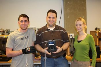
Mozart's Right Hand is a musical instrument capable of playing two full octaves of the Diatonic Scale. The user wears a glove on his right hand and uses motions of the hand and fingers to create different notes that are played with a speaker. The pitch of the note is controlled by the orientation of the user's hand as he rotates it ether from the wrist, the elbow, or the shoulder. The LCD on the front of the box tells the user the pitch that corresponds to his or her current hand orientation. When the user touches together his thumb and index finger, the speaker plays the tone. A video of Mozart's Right Hand in action is available on YouTube.
The Team
- Colleen Fryer ( colleenfryer2008 at u dot northwestern dot edu ), Mechanical Engineering Graduate Student
- Sean Wood ( seanwood2010 at u dot northwestern dot edu ), Mechanical Engineering Junior
- Mat Kotowsky (kotowsky at northwestern dot edu), Civil Engineering Graduate Student
Theory of Operation
Mozart's Right Hand plays all of the notes, including sharps and flats, between and including C5 and C7 (where C4 is "Middle C"). Each of these notes has a specific frequency associated with it; for example: C6 has a frequency of 1046.50 Hz. Other notes' frequencies are available at http://www.phy.mtu.edu/~suits/notefreqs.html. If signal whose voltage is a 1046.50 Hz sine wave is passed through a speaker, the speaker will play C6. Increasing the frequency will raise the pitch, decreasing it will lower the pitch. Increasing the amplitude will cause the volume of the note to go up, decreasing it will cause the volume to go down.
Orientation of the Hand Relative to Gravity
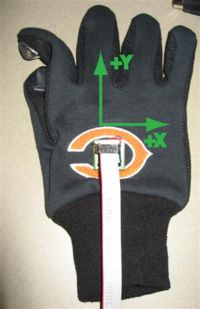
The pitch of a note is determined by measuring gravitational acceleration in two axes. The Y-axis runs along the user's arm with positive being toward the fingertips. The X-axis is orthogonal to the Y axis and lies in the plane of the palm of the hand. The pitch is decided by first measuring the gravitational acceleration in the Y direction. If the Y acceleration is 0g, the palm is parallel to the floor. If the Y acceleration is 1g, the palm is perpendicular to the floor with the fingertips pointing towards the floor. If the Y acceleration is -1g, the plan is perpendicular to the floor with the fingertips pointed straight up. When the fingertips are pointed straight down (1g), Mozart's Right Hand produces its lowest possible note: C5. When the fingertips are pointed straight out (0g), it produces its mid-rage note: C6. When the fingertips are pointed straight up (-1g), it produces its highest possible note, C7.
The X-axis is used to determine whether a note is sharp or flat. If the X axis measures 0g, the note is played naturally with no sharps or flats. If the X axis measures a positive gravitational acceleration, the user is tipping his hand to the right and the note is played sharp. If the X axis measures a negative gravitational acceleration, the user is tipping his hand to the left and the note is played flat.
For both the X and Y axes, the actual values used to determine the thresholds between notes were determined empirically. They appear in the code below.
Effect of Centripetal Acceleration
During typical use, the user's hand remains stationary and the only effect on the pitch is the glove's orientation with respect to gravity. It is possible, however, that the user will want to play a note while simultaneously moving his hand. The speaker will play different tones as the user moves his hand through the different orientations. During this type of playing, the acceleration measured by the accelerometer is not only due to gravity but due to the effect of centripetal force caused by the hands rotation about the user's wrist, elbow, or shoulder. If one assumes that such motion is uniform and circular about its center, then the acceleration measured during motion is a superposition of the acceleration due to gravity and the acceleration toward the center of rotation: ![]() .
.
The average length of a human hand is approximately 180mm (from http://en.wikipedia.org/wiki/Hand), so the distance between the accelerometer and the wrist is about half of that: 90mm. If the fastest a user moved his hand from straight down to straight up is one second, its total distance traveled would be one half of the circumference of a circle with a radius of 90mm: approximately 280mm, for a velocity of about 280mm per second. Therefore, the acceleration towards the wrist would be approximately 0.9 meters per second squared. This is less than one tenth of a g, so a user would not experience a significant change in note pitch due to centripetal acceleration while rotating at the wrist.
The same calculation could be carried out for playing Mozart's Right Hand by rotating through the elbow or the shoulder.
Hardware
Mozart's Right Hand is comprised of two main components: the input glove and the desktop box. The glove carries the sensors that determine which note is played and when it is played. The desktop box contains all of the intelligence to read the sensors, translate them into frequencies, and drive the speaker. The glove is connected to the box by a 10-position ribbon cable.
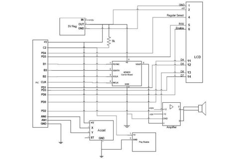
Circuit Diagram
Glove
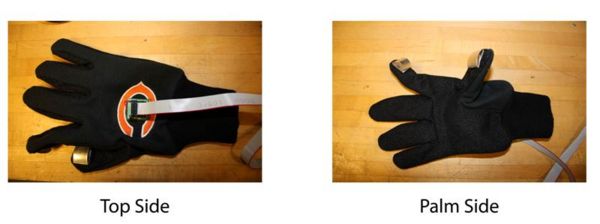
The glove contains a dual axis accelerometer and a set of fingertip contacts between the thumb and the forefinger. These components are connected together via hookup wire that runs through the finger, thumb, and palm of the glove, then back to the desktop box via a 10-pin ribbon cable.
Accelerometer
The accelerometer is an ADXL-320 MEMS accelerometer configured for dual-axis use. Though it has a range of +/-5g, it is only used in the +/-1g range. The accelerometer has pins V+, GND, X, Y, and a test pin. The test pin, though connected to the ribbon cable, is not used. The X and Y pins provide ratiometric analog output. V+ is connected to a 5 VDC output coming from a regulator inside of the desktop box. The GND pin is connected to one end of the Play Enable switch closure and also to the digital ground inside of the desktop box. The accelerometer is sewn to the top of the glove using the signal wires through the mounting holes on the carrier board.
Play Enable
The Play Enable functionality is implemented with two thin strips of aluminum that are shaped into semicircles and attached to the thumb and index fingertips of the glove with double-stick tape. Sections of hookup wire are soldered to these fingertip contacts and run through the fingers of the glove to the accelerometer. There, one fingertip contact is attached to ground and the other runs through the ribbon cable to be connected to a digital input pin on the microcontroller.
Desktop Box
Microcontroller and Protoboard
Mozart's Right Hand is built on the Microchip PIC 18F4520. The design uses a 40 MHz clock and takes advantage of the software-controlled SPI interface to program the function generator, two ADC pins to read the accelerometer, one digital input pin to read the play enable contacts, and several digital output pins to drive the LCD. The circuit board is powered using a Meanwell desktop power supply that produces +12, -12, and +5 volts DC with a total power output of 26 watts. Mozart's Right Hand makes use of the +/-12 volt power for its audio amplifier and uses the +12 volts to power a TO-220 7805 5V regulator.
Function Generator
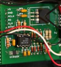
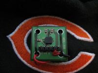
The AD9833 function generator is a small chip that can generate square waves, sine waves, and triangle waves of varying frequencies. It communicates using a 16-bit version of SPI. The code to operate the function generator is a re-use of the code from the Guitar Tuning Project. Mozart's Right Hand uses a sine wave to drive its speaker. When the AD9833 is configured to produce a sine wave output, instead of oscillating about zero, the sine wave oscillates around 0.3 volts with an amplitude of 0.3 volts. The LIMS-designed AD9833 carrier board uses an LM6132 operational amplifier to line-shift and amplify the signal such that it oscillates about 0 volts with an amplitude of 2 volts. This signal is not strong enough to generate a suitable tone, so it is passed through another amplifier, as described below, before going to the speaker.
The LIMS carrier board also includes various components that provide for signal conditioning, power regulation, and reverse- and short-current protection.
Amplifier and Speaker
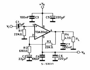
Mozart's Right Hand plays its tones through a 4-inch 4-watt 4-ohm speaker. The output of the function generator is not sufficient to drive this speaker at a reasonable volume. To compensate for this, further audio amplification is necessary. The design uses a TDA-2040 20-watt amplification chip in a T-220 package. Use of a heat sink is crucial as this chip can generate a great deal of heat even at low volumes. The data sheet for the amplifier chip contains a diagram for a circuit to test the amplifier. This test circuit proved to be adequate for the needs of the project and is implemented in the final design.
In the wiring diagram pictured to the right, represents the input signal to the amplifier -- in this case, the output of the function generator after it has been passed through a 100K-ohm knob potentiometer for volume control. and represent the +12 and -12 volt input from the DC power supply. represents the speaker. Note that in this diagram, a capacitor with a white side is polarized with white denoting the positive terminal.
LCD
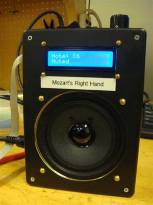
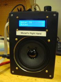
Mozart's Right Hand makes use of a 16 by 2 character LCD with a blue backlight. This LCD is HD44780 compatible, as described in the LCD interfacing article on the Mechatronics Wiki. During operation of Mozart's Right Hand, the LCD will, at all times, display the note that corresponds to the current orientation of the glove. If the finger contacts are not touched together, the LCD will also display "Muted" to indicate that no sound should be coming out of the speaker. When the finger contacts are touched together, the word "Muted" disappears and the speaker will play the note indicated.
Enclosure
The enclosure for Mozart's Right Hand is a Radio Shack 8"x6"x3" project box with several customized ports cut into it using an automatic milling machine. The front of the box has cutouts for the speaker and the LCD which are both mounted with machine screws and nuts.
Top
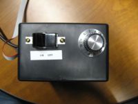
On the top of the box, there is a large rocker switch for power. This DPDT switch will break the supply of +12 and -12 volts coming from the power supply. Also on the top of the box is a numbered knob to control volume. This knob is a 100K-ohm potentiometer that scales the output of the function generator as it is going into the audio amplifier. The knob is secured to the enclosure with epoxy.
Left Side
On the left side of the box is a 5-pin circular DIN power connector that mates with the desktop power supply. Because a significant amount of force is required to mate the power connector with the power supply, the connector is secured to the enclosure with a custom-machined metal plate. Also on the left side of the box is the 10-pin rectangular plug that accepts the ribbon cable from the glove. This header is keyed so that the ribbon cable cannot be inserted backwards. It is secured to the enclosure with epoxy.
Software
The software that powers Mozart's Right Hand runs in an infinite loop in which it
- Determines the current orientation of the glove
- Maps the orientation of glove to a note
- Determines whether it should play the note or be silent
- Plays the note (if necessary)
The full code contains all of the hardware initializations and pin configurations.
Frequency Code Discussion
These comments in the code explain how the notes are mapped.
/* Frequency Discussion

See this page: http://www.phy.mtu.edu/~suits/notefreqs.html

We want to have two octaves of usable notes.  Based on playing with the speaker
and a function generator, it would seem that our best octaves are going to be 5 and 6,
that is, C5 up through C7.

C5 frequency is: 523.25 Hz
C7 frequency is: 2093.00 Hz

Adjusting the orientation of the ADXL-320 yields maximum and minimum ADC values:

Straight Up:   111   -> C7
Straight Out:  127   -> C6
Straight Down: 143   -> C5

All of the notes:

Note        Frequency (Hz)
C5          523.25
C#5/Db5     554.37
D5          587.33
D#5/Eb5     622.25
E5          69.26
F5          698.46
F#5/Gb5     739.99
G5          783.99
G#5/Ab5     830.61
A5          880
A#5/Bb5     932.33
B5          987.77
C6          1046.5
C#6/Db6     1108.73
D6          1174.66
D#6/Eb6     1244.51
E6          1318.51
F6          1396.91
F#6/Gb6     1479.98
G6          1567.98
G#6/Ab6     1661.22
A6          1760
A#6/Bb6     1864.66
B6          1975.53
C7          2093
*/

float note_frequencies[26] = {
   523.25, 554.37, 587.33, 622.25, 659.26, 698.46, 739.99, 783.99, 830.61, 880, 932.33, 987.77,
   1046.5, 108.73, 1174.66, 1244.51, 1318.51, 1396.91, 1479.98, 1567.98, 1661.22, 1760, 1864.66, 1975.53,
   2093, 0
};

char note_names[26][26] = {
   "C5", "C#5/Db5", "D5", "D#5/Eb5", "E5", "F5", "F#5/Gb5", "G5", "G#5/Ab5", "A5", "A#5/Bb5", "B5",
   "C6", "C#6/Db6", "D6", "D#6/Eb6", "E6", "F6", "F#6/Gb6", "G6", "G#6/Ab6", "A6", "A#6/Bb6", "B6",
   "C7", "Silence"
};
Reading the Accelerometer and Selecting the Note
This block of code will read both axes of the accelerometer and map the results a note. 4096 samples are taken from the Y-axis and averaged. This effectively creates a low-pass filter that eliminates noise from the accelerometer output. The note selected will be an integer which is then used to index into arrays of note frequencies and names.
// This function will read the accelerometer then return the frequency
// that we should put out to the speaker
int8 get_note(void)
{
   int32 i;
   int32 adc_value;
   int8 note;
   float adc_value_float;     // How Hungarian!

   set_adc_channel(0);
   delay_us(10);           // give ADC time to switch to new channel

   // Take 4096 samples of ADC and average them
   adc_value = 0;
   for(i=0; i<4096; i++)
   {
      adc_value += read_adc();
   }

   adc_value_float = (float) adc_value / 4096;

   //This is a big if/else block to decide which note to play and spit out on the LCD
   if(adc_value_float < 113.5)
      note = 24;   // C7
   else if(adc_value_float < 115)
      note = 23;   // B6
   else if(adc_value_float < 117)
      note = 21;   // A6
   else if(adc_value_float < 119)
      note = 19;   // G6
   else if(adc_value_float < 121)
      note = 17;   // F6
   else if(adc_value_float < 123)
      note = 16;   // E6
   else if(adc_value_float < 125)
      note = 14;  // D6
   else if(adc_value_float < 127)
      note = 12;  // C6
   else if(adc_value_float < 131)
      note = 11;  // B5
   else if(adc_value_float < 133)
      note = 9;  // A5
   else if(adc_value_float < 135)
      note = 7;  // G5
   else if(adc_value_float < 137)
      note = 5;  // F5
   else if(adc_value_float < 139)
      note = 4;  // E5
   else if(adc_value_float < 141)
      note = 2;  // D5
   else
      note = 0;  // C5

   // Determine if note should be sharp or flat

   set_adc_channel(1);
   delay_us(10);           // give ADC time to switch to new channel
   adc_value = read_adc();

   if (adc_value >= 135)   // Right is sharp
   {
      if (note < 24) // Don't go above C7
         note++;
   }

   else if (adc_value <= 127) // Left is flat
   {
      if (note > 0) // Don't go below C5)
         note--;
   }

   return note;
}
Creating the Signal
This function instructs the AD9833 function generator to put out a sine wave of the appropriate frequency.
void set_frequency(float freq)
{
   // Based on the code from the Guitar Tuning Project:
   // http://hades.mech.northwestern.edu/wiki/index.php/Guitar_Tunning_Project

   int32 conv_freq;
   int16 lsb, msb;

   conv_freq = (int32)(freq*6.7108864);               // 2^28/CLOCK = (2^28)/(40*10^6) = 6.7108864
   lsb= (int16)(conv_freq)&(0b0011111111111111);      //(Get the lowest 14 bits of conv_freq)
   msb= (int16)(conv_freq>>14)&(0b0011111111111111);   //(get the 14 most significant bits out of 28 bits conv_freq)

   spi_xfer(0x2100);       // reset, tell it to expect two writes-*
   spi_xfer(0x4000 | lsb); // lsb in freq0
   spi_xfer(0x4000 | msb); // msb in freq0
   spi_xfer(0x0000);       // unreset, set up write
}
Playing Notes
This code is the main program loop. The program will not instruct the AD9833 to change frequencies unless either the hand orientation has changed or if the fingers have been opened or closed. If the frequency is allowed to be reset every time the sensor input is polled, the speaker makes will make repeating clicking noises. The LCD is updated every polling interval regardless of whether the note has changed or the fingers have opened or closed.
   // Main Program Loop
   while(TRUE)
   {
      playDisabled = input(PIN_C2);
      note = get_note();
      printf("Note: %s\t",note_names[note]);
      printf(lcd_putc, "\fNote: %s\n",note_names[note]);
      if(playDisabled)
      {
         printf("Muted");
         printf(lcd_putc,"Muted");
         if(!oldPlayDisabled) // Don't do this if we're not changing from un-muted to muted.
            set_frequency(0);

      }
      else
      {
         if ((note != old_note) || (playDisabled != oldPlayDisabled))  // Don't do this unless we're changing notes.
            set_frequency(note_frequencies[note]);
      }

      old_note = note;
      oldPlayDisabled = playDisabled;

      printf("\n\r");
   }
Further Reading and References
The Project
- Full Mozart's Right Hand Code: mrh_code.c
- YouTube video of Mozart's Right Hand in action
Theory References
- Notes and frequencies of the diatonic scale
- Wikipedia: Centripetal Force
- Wikipedia: The Hand
- Wikipedia: Serial Peripheral Interface (SPI) bus)
Component Data Sheets
- AD9833 data sheet
- Microchip PIC18F4520
- TDA-2040 20-watt amplifier
- LCD interfacing article on the Mechatronics Wiki
