Getting Started with PIC32
This page details getting started with the PIC32 board.
Please complete the software section prior to lab 1.
In lab 1, you will assemble a NU32 board, install a bootloader and create a Hello World Program.
Software
This section discusses the software that must be installed on your computer. This software is only compatible with Windows. We are going to install MPLAB (software used for editing, compiling, and debugging code), the C32 compiler (software to create the program) and the Microchip Applications Library (common source files for programming).
1. Download MPLAB IDE vX.XX Full Release Zipped Installation located near the bottom of this page. You can save the zip file temporarily to the desktop; you will delete it after installation. Extract the files from the zip file to create a folder on your desktop. Double-click on the setup launcher, run it, and choose "complete setup." Let it install in the default location. (Do not install HITEC-C when prompted.) If MPLAB IDE Document Select appears, you can just close it. Now the MPLAB IDE is installed and you can delete the zip file and extracted folder from your Desktop.
2. Download the MPLAB C Compiler for PIC32 vX.XX Academic Version located near the bottom of this page (the academic version is free). Click "Run" and let it install in the default location.
3. Download the Microchip Applications Library here. This zip file is the library version released on 11-18-2009. More recent versions may be downloaded here but the files may not work with the code listed on the wiki. Save the zip file to your desktop and extract the files. Run the installer and install to the default. Now you can delete the zip file and extracted folder. Note: When installing this library, Microchip may prompt you to install .Net software. Click yes if this happens.
Board Assembly
The NU32 development board you are going to assemble already has a PIC32 microcontroller soldered on the board. You will be soldering the rest of the components.
Collect the following components from the PIC32 supply bin.
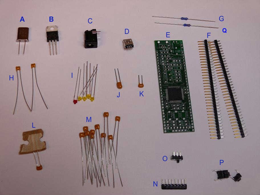
| Part Label | Part Name | Quantity | Vendor | P/N | Description | |||||
|---|---|---|---|---|---|---|---|---|---|---|
| A | 8.0 MHz Crystal | 1 | Digikey | X979-ND | ||||||
| B | 3.3 V Regulator | 1 | Digikey | LD1117V33 | Input: 4.75 ~ 10 V; Output: 3.3V, 950 mA | |||||
| C | Barrel Connector 2.5mm ID | 1 | Digikey | CP-102BH | ||||||
| D | Mini USB - B Socket | 1 | Digikey | WM17115-ND | ||||||
| E | NU32 Board | 1 | NU | |||||||
| F | 36 Pos Single Row Header Pins | 2 | Digikey | WM6536 | You will cut these to two rows of 29 pins for the long edges of the board. You will also need a leftover 5-pin header to mount at the short end of the board away from the USB connector. These pins will point upward, opposite the pins on the long edge of the board. This 5-pin header will be used to program the bootloader on the PIC32. | |||||
| G | 330 Ohm Resistor | 1 | Digikey | 332XBK-ND | ||||||
| H | 22 pF Capacitor | 2 | Digikey | 478-4846-ND | ||||||
| I | LEDs | 5 total | Digikey |
| ||||||
| J | 10 uF Capacitor | 1 | Digikey | 399-3548-ND | Polarized | |||||
| K | 0.33 uF Capacitor | 1 | Digikey | 399-4299-ND | ||||||
| L | 1 uF Capacitor | 1 | Digikey | BC1162CT-ND | ||||||
| M | 0.1 uF Capacitor | 10 | Digikey | 478-3192-ND | ||||||
| N | 1K Ohm Resistor Array | 1 | Digikey | 770-81-R1KP-ND | ||||||
| O | Sub Miniature Slide Switch | 1 | Digikey | 401-2001-ND | ||||||
| P | Reset Button | 3 | Digikey | CKN9102-ND | ||||||
| Q | 10K Ohm Resistor | 1 | Digikey | 10.0KXBK |
The PIC32 is already soldered to the board.

Begin soldering components, ending with the header pins.
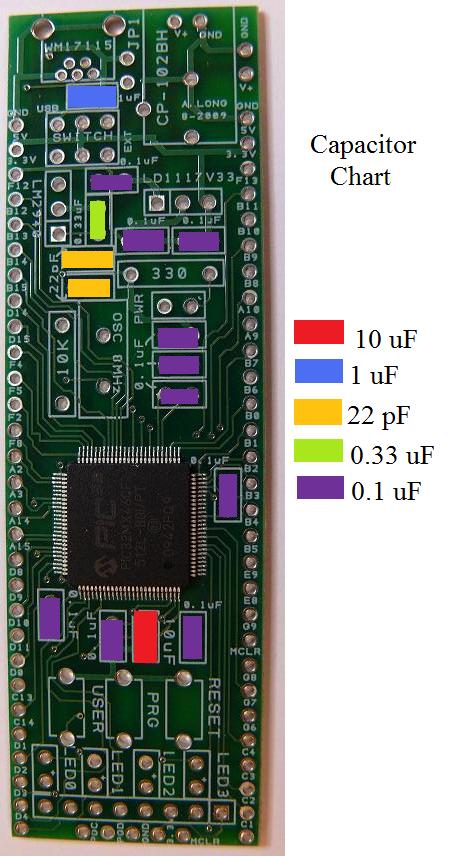
The capacitor labels can be hard to read, they are color coded here:
Several components need to be soldered with the proper orientation.
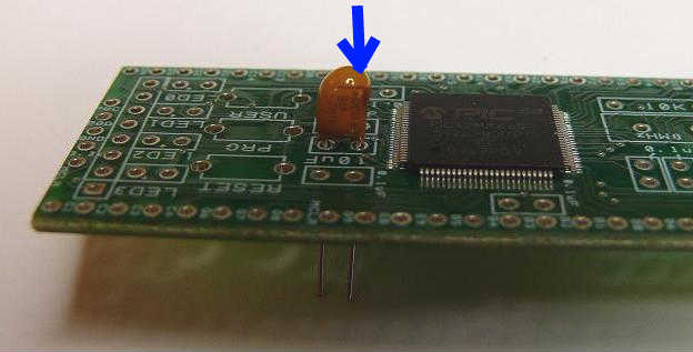
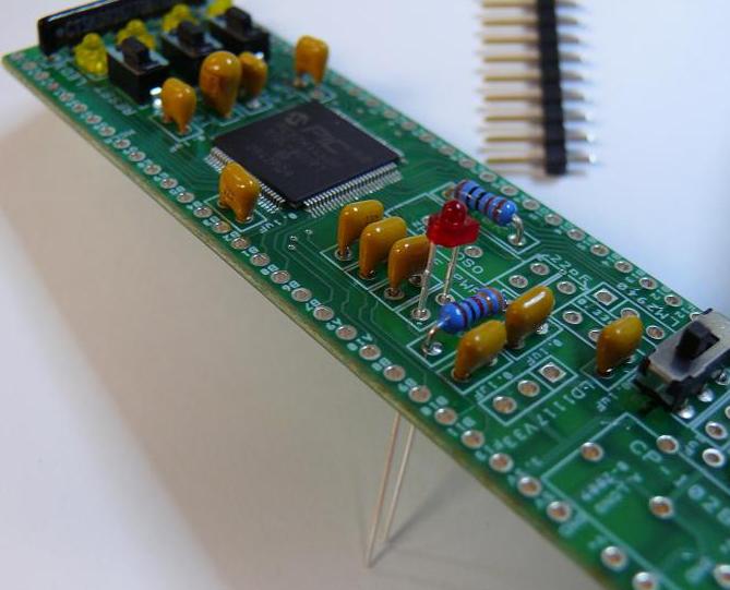
The 10 uF capacitor needs to be soldered with the positive lead towards the PIC.
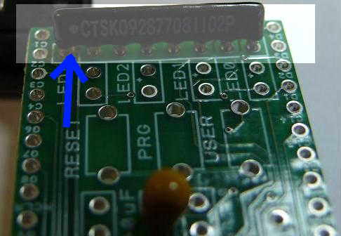
The resistor array needs to have the side with the dot facing the long end of the board.
The indicator LEDs need to have their positive leads toward the end of the board.
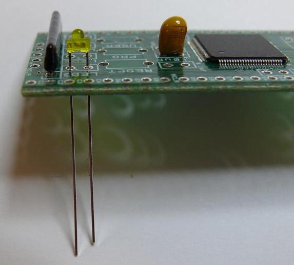
The power LED needs to have its positive lead facing the close edge of the board.
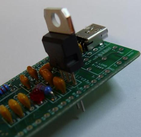
The 3.3V regulator needs to have its back side facing the power jack.
The finished board looks like this:

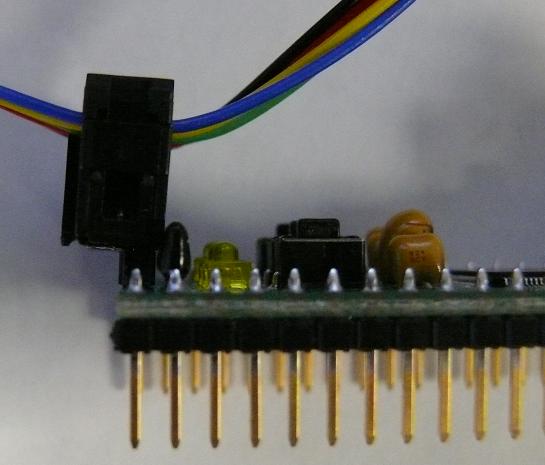
Note to program the bootloader onto the board, the programming cable can only be plugged into the last five header pins one way:
Bootloader
Note: If you're in lab with the TA, you can ask the TA to install the bootloader for you and skip this step. Once the bootloader is installed on your PIC, you should not have to install it again. This step requires the Microchip ICD2 programmer.
A bootloader is a program that enables you to easily install programs on the PIC32 using only a USB cable. Normally, an external programmer is needed for programming the PIC. The bootloader takes hex files created by the MPLAB compiler and programs them on the PIC. Hex files are binary representations of the c code. See the wikipedia page for Hex files here for more information.
Follow these directions to install a bootloader on your PIC.
First Program
We are first going to test that you installed the bootloader correctly.
- Download this HelloWorld zip file and extract the hex. (This code flashes all of the LEDs at a 1 second period, if you hold down the USER button the period changes)
- Use these directions to load a hex File with the bootloader.
Next, we are going to make a different Hello World program from scratch.
- Follow the directions here to code and program Hello World on to the PIC32 using the bootloader.