Building the blue board
From Mech
Back to Northwestern Design Competition
The blue board stacks with the black board and the green board.
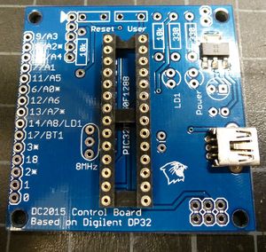
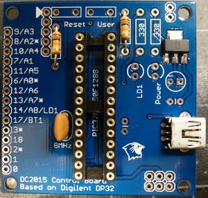
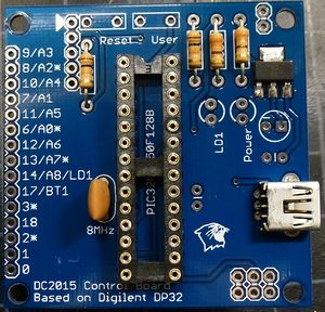
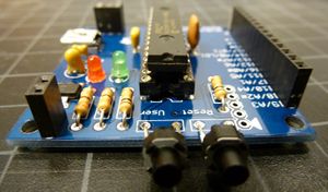
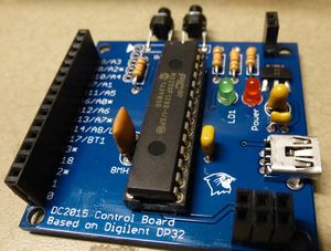
The DC2015 Control board
The blue board is a clone of the chipKIT DP32 by Digilent Inc.
It uses the PIC32MX250F128B, running at 40MHz with 128k flash and 32k RAM. The blue board breaks out 15 I/O pins, including 9 analog input and 5 PWM.
The schematic for the board is:
| Pin | Functionality |
| 9/A3 | Digital pin 9, by default analog input 3 |
| 8/A2* | Digital pin 8, by default analog input 2, capable of PWM |
| 10/A4 | Digital pin 10, by default analog input 4 |
| 7/A1 | Digital pin 7, by default analog input 1 |
| 11/A5 | Digital pin 11, by default analog input 5 |
| 6/A0* | Digital pin 6, by default analog input 0, capable of PWM |
| 12/A6 | Digital pin 12, by default analog input 6 |
| 13/A7* | Digital pin 13, by default analog input 7, capable of PWM |
| 14/A8/LD1 | Digital pin 14, by default analog input 8, hardwired to the green LED LD1 |
| 17/BT1 | Digital pin 17, hard wired to the User button BT1 |
| 3* | Digital pin 3, capable of PWM |
| 18 | Digital pin 18 |
| 2* | Digital pin 2, capable of PWM |
| 1 | Digital pin 1 |
| 0 | Digital pin 0 |
Power
The blue board is powered by a 5V USB source, using a USB A to mini B cable.
The PIC32 is a 3.3V chip - do not put 5V on any of the pins, especially the analog inputs!
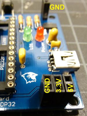
5V, 3.3V, and ground are broken out to be used for sensors and actuators.
Image of power outs
Assembly
Be sure to read up on How to solder
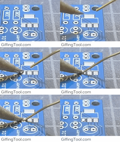
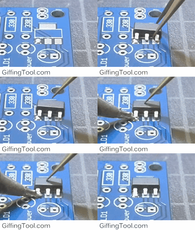
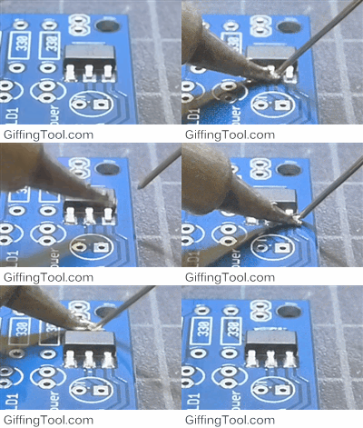
- Solder the 3.3V surface mount regulator
- Solder the USB mini B connector
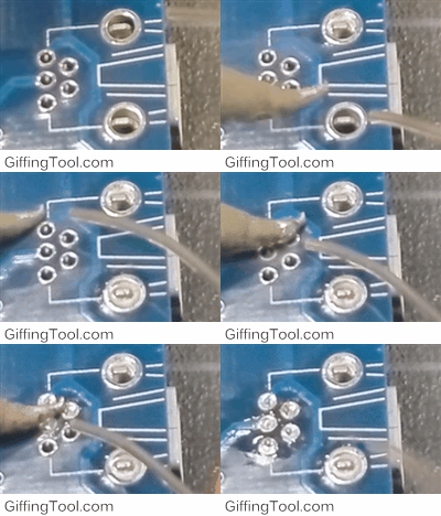
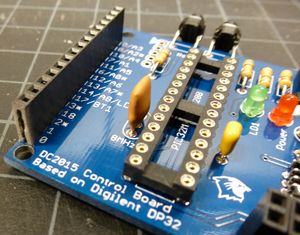
- Solder the 28 pin DIP adapter
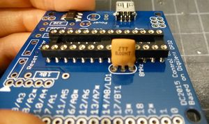
- Solder the 8MHz crystal resonator
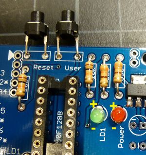
- Solder the 10k and 330 resistors
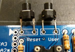
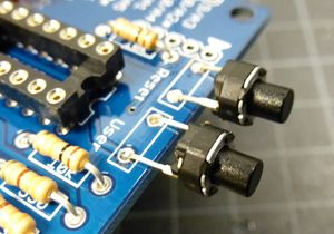
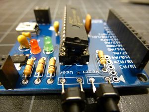
- Solder the push buttons Reset and User, make sure they are accessible from the side
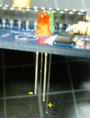
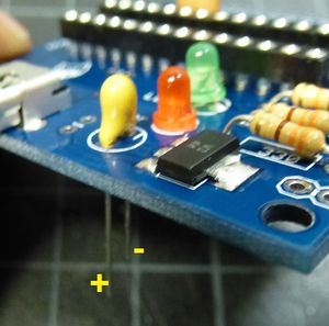
- Solder the green LED LD1 and the red LED Power, note the polarity
- Solder the 10uF capacitor, note the polarity
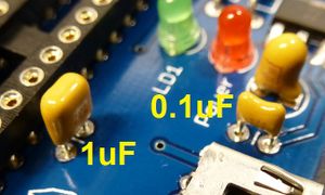
- Solder the 0.1uF capacitor and the 1uF capacitor
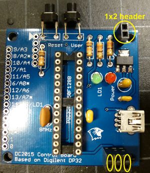
- Add the 2x1 headers for power
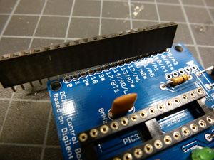
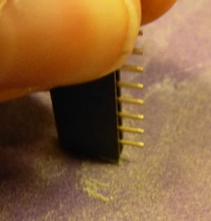
- The 1x21 header is too long, needs to be 1x15
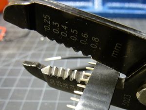
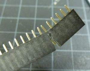
- Cut away the 16th pin
- Sand the rough plastic edge if necessary and solder
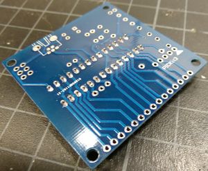
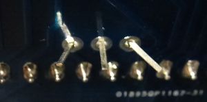
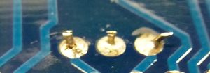
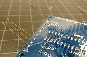
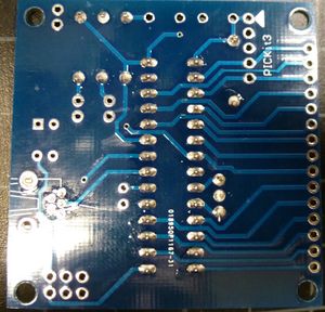
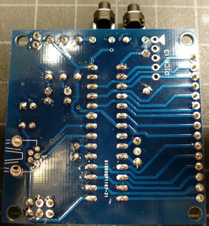
- The bottom of your board should be nice and clean, no sharp wires and nice solder filets
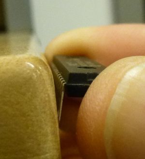
- Put the PIC32 in, but notice the pins do not fit
- Bend the pins simultaneously against a table
- Push the chip in and the board is done!
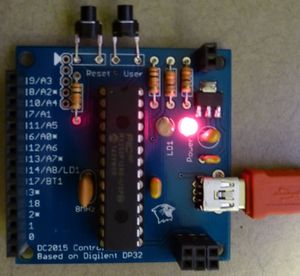
- Plug in a mini USB cable. IF the red light turns on, and the chips do not get hot, the board is ready to have the bootloader installed (see Nick)
