Uploads by EricNickel
From Mech
Jump to navigationJump to searchThis special page shows all uploaded files.
| Date | Name | Thumbnail | Size | Description | Versions |
|---|---|---|---|---|---|
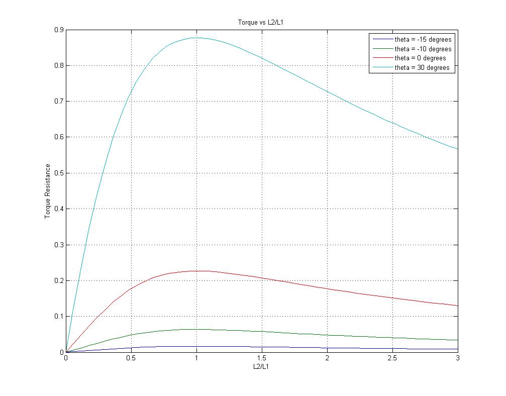
| 23:28, 20 March 2008 | Progstiffjointtorque2d.jpg (file) |  |
71 KB | 2D plots of the torque produced at the joint for different angles and L2 distances | 1 |
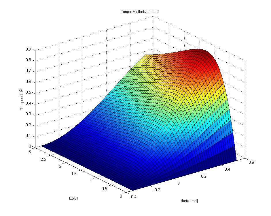
| 23:27, 20 March 2008 | Progstiffjointtorque3d.jpg (file) |  |
136 KB | 3D plot of the torque produced at the joint for different angles and L2 distances | 1 |
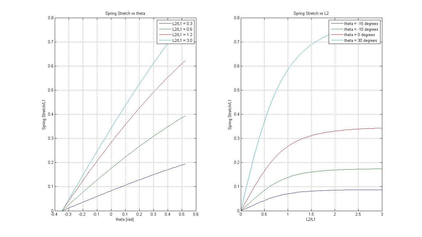
| 23:22, 20 March 2008 | Progstiffjointstretch2d.jpg (file) |  |
112 KB | 2D plots of the spring stretch for different angles and L2 distances | 1 |
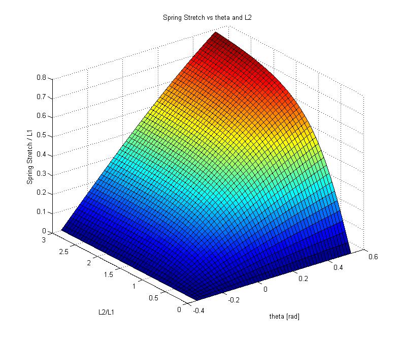
| 23:21, 20 March 2008 | Progstiffjointstretch3d.jpg (file) |  |
120 KB | 3D plot of the spring stretch for different joint angles and L2 distances | 1 |
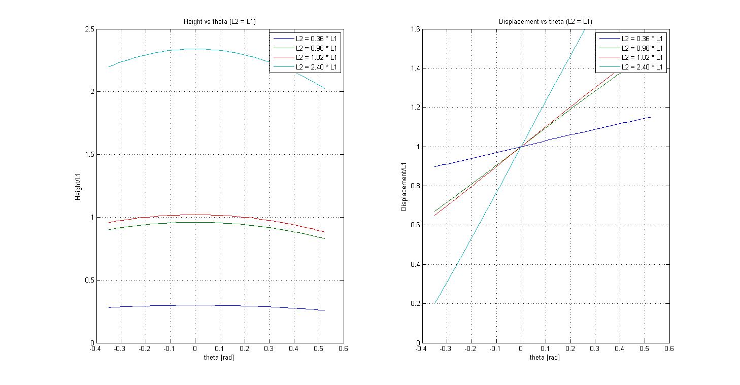
| 22:36, 20 March 2008 | Progstiffjointloc2d.jpg (file) |  |
110 KB | 2D plots of the height and lateral location of the rotating insertion point with respect to the static insertion point. | 1 |
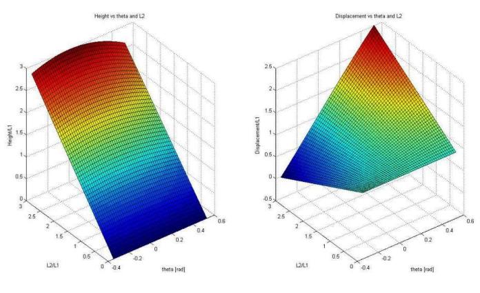
| 22:35, 20 March 2008 | Progstiffjointloc3d.jpg (file) |  |
53 KB | 3D plots of the height and lateral displacement (L1+a) of the rotating insertion point with respect to the static insertion point | 1 |
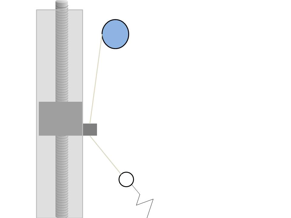
| 22:14, 20 March 2008 | Rotatinginsertion.jpg (file) |  |
23 KB | A diagram of the rotating insertion point and the track it slides along, as well as the pulley which spools the cable in and out. | 1 |
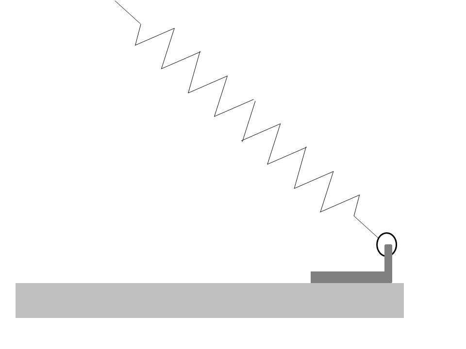
| 22:12, 20 March 2008 | Staticinsertion.jpg (file) |  |
15 KB | A diagram of the static insertion point of the programmable stiffness joint | 1 |
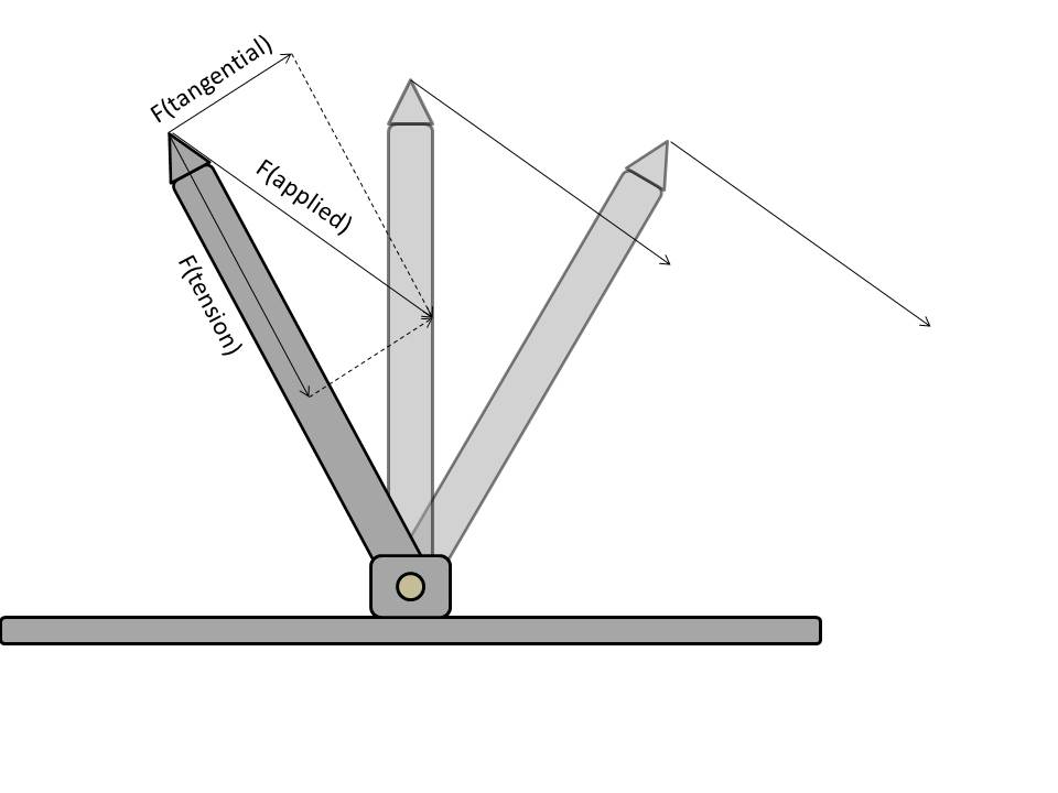
| 20:50, 20 March 2008 | Vectordecomp3.jpg (file) |  |
33 KB | Image of a constant applied force decomposed to tangential and parallel components for the third of three angles | 1 |
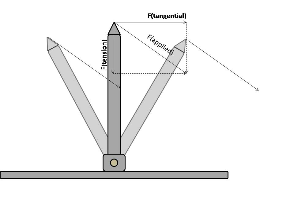
| 20:49, 20 March 2008 | Vectordecomp2.jpg (file) |  |
35 KB | Image of a constant applied force decomposed to tangential and parallel components for the second of three angles | 1 |
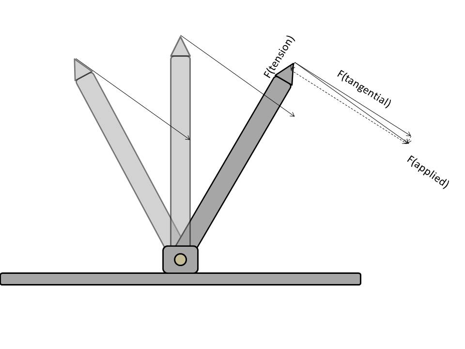
| 20:49, 20 March 2008 | Vectordecomp1.jpg (file) |  |
37 KB | Image of a constant applied force decomposed to tangential and parallel components for one of three angles | 1 |
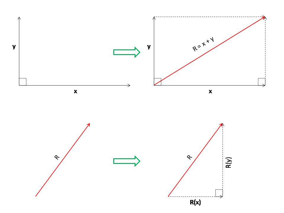
| 20:47, 20 March 2008 | Vectordecomp.jpg (file) |  |
27 KB | Diagram demonstrating vector decomposition | 1 |
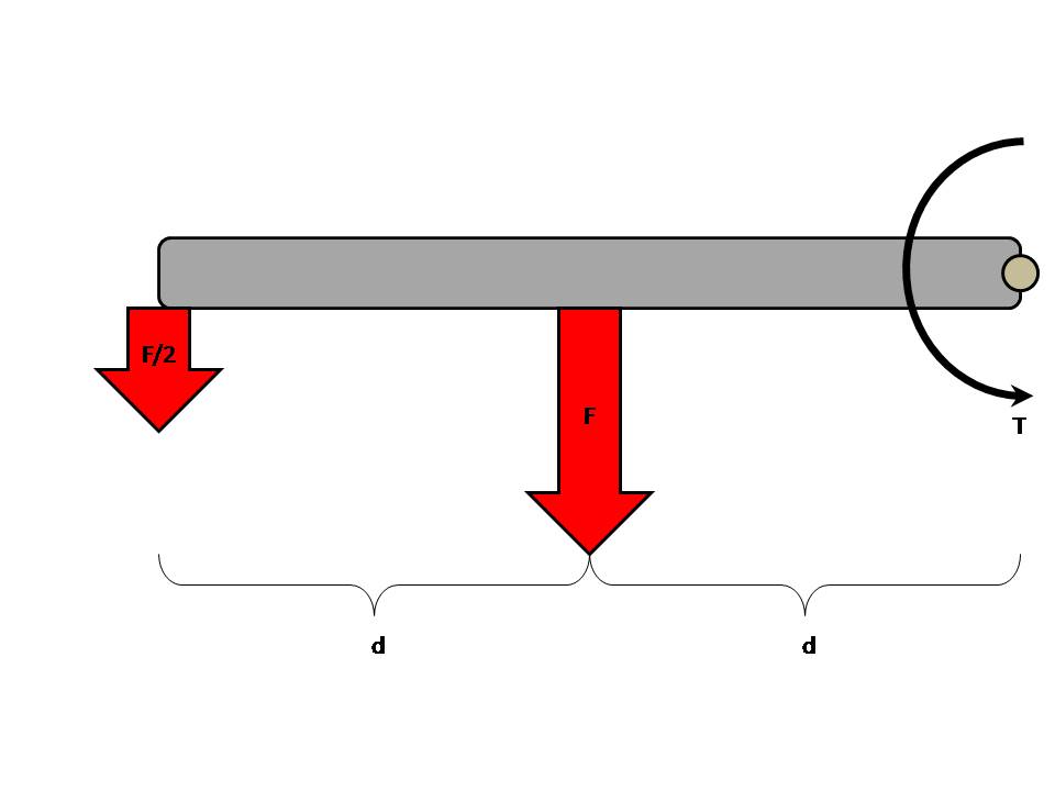
| 20:08, 20 March 2008 | Torquediagram.jpg (file) |  |
27 KB | Diagram demonstrating the relationship between torque, force, and moment arm distance. | 1 |
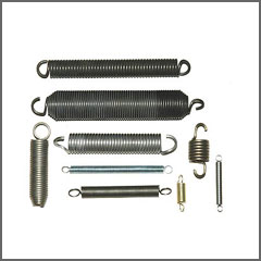
| 19:03, 20 March 2008 | Extensionsprings.jpg (file) |  |
10 KB | Image of linear coil extension springs | 1 |
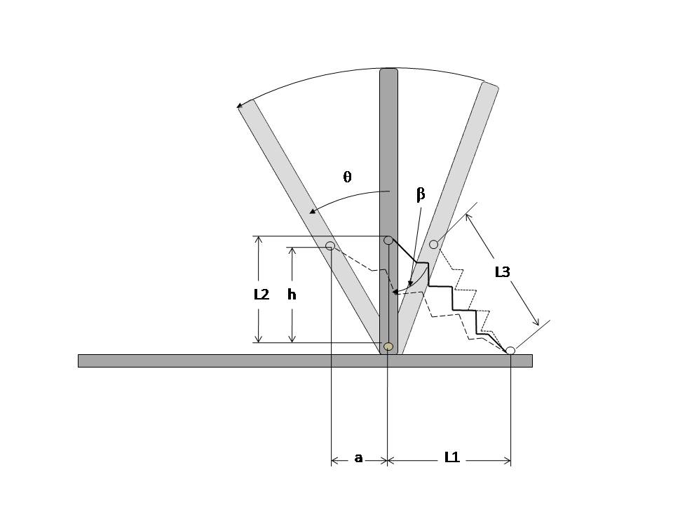
| 15:52, 20 March 2008 | ProgStiffJointConcept.jpg (file) |  |
31 KB | Diagram showing the variables used in the theoretical computations for the variable stiffness joint. | 1 |
| 14:25, 20 March 2008 | Stiffnesstheory.m (file) | 6 KB | Stiffness theory computations and graphs for the variable stiffness joint | 1 | |
| 15:42, 19 March 2008 | ProgStiffJointTorque.jpg (file) |  |
71 KB | Change in torque produced at the joint by the spring tension for changes in insertion point ratio | 1 |
| 15:41, 19 March 2008 | ProgStiffJointL3.jpg (file) |  |
112 KB | Change in spring extension as a function of insertion point ratio and angle | 1 |
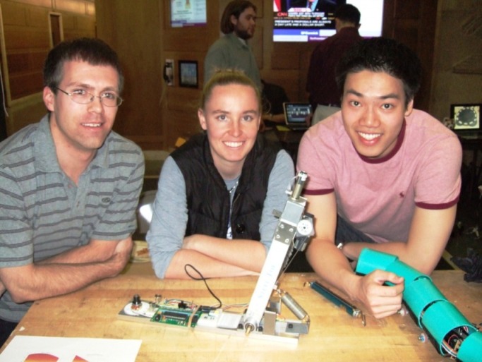
| 11:20, 19 March 2008 | ProgStiffJointTeam.jpg (file) |  |
99 KB | The engineers behind the Programmable Stiffness Joint. From left to right: Eric Nickel, Amanda Care, and James Yeung. | 1 |
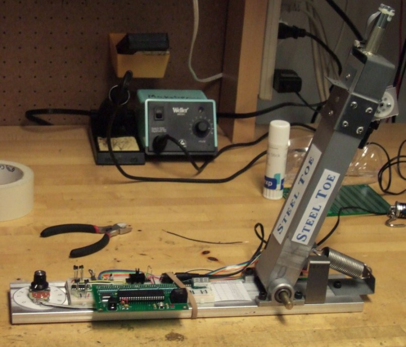
| 11:12, 19 March 2008 | SteelToePic.jpg (file) |  |
113 KB | Main image of the Programmable Stiffness Joint. | 1 |
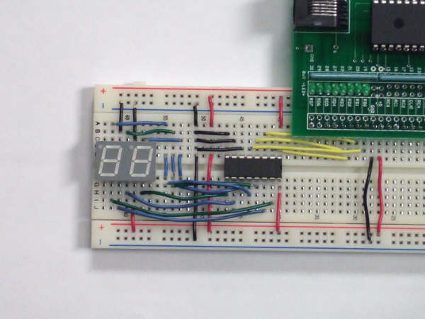
| 18:46, 5 February 2008 | 7SegmentCircuit4.jpg (file) |  |
120 KB | Rotated and labeled close up wiring diagram for 7-segment display | 1 |
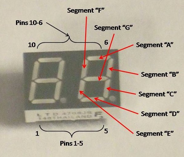
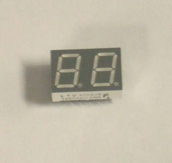
| 18:40, 5 February 2008 | LTD4708JS Pic1.jpg (file) |  |
75 KB | Labeled image of LTD 4708JS 7-segment display module | 1 |
| 18:39, 5 February 2008 | 4708JS Pic1.jpg (file) |  |
75 KB | Labeled Image of the LTD 4708JS 7-segment display | 2 |
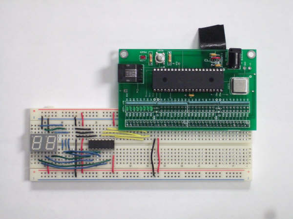
| 15:56, 5 February 2008 | 7SegmentCircuit3.jpg (file) |  |
34 KB | Close-up of the wiring for the 7-segment display module which has the digit select hard wired to only display one digit | 1 |
| 12:50, 5 February 2008 | 7SegmentCircuit1.jpg (file) |  |
32 KB | 1 | |
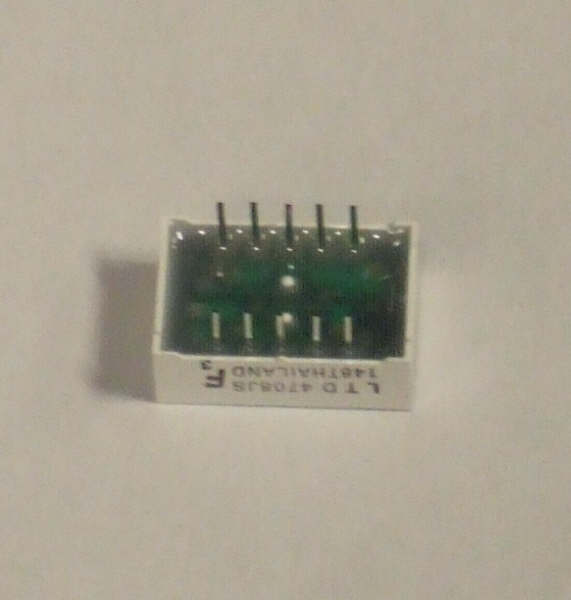
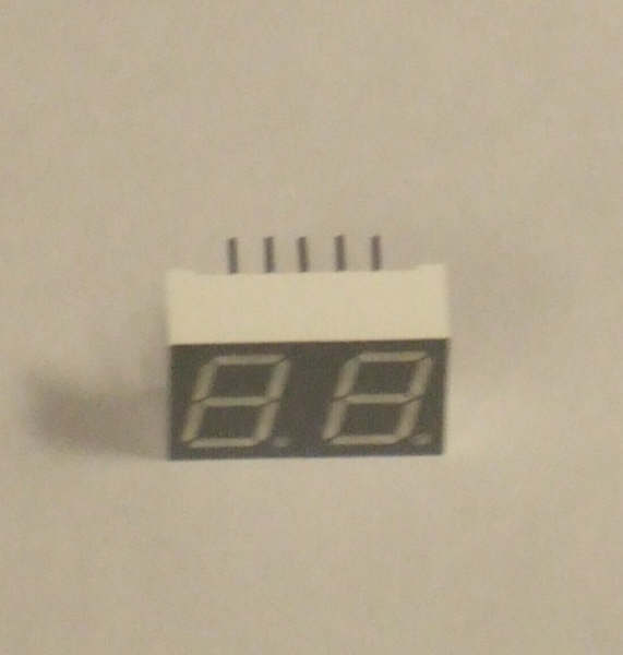
| 12:43, 5 February 2008 | 4708JS Pic2.JPG (file) |  |
19 KB | A view of the LTD 4708JS 7-segment display from the bottom | 1 |
| 12:42, 5 February 2008 | 4708JS Pic1.JPG (file) |  |
18 KB | An image of the LTD 4708JS 7-segment display | 1 |
| 12:41, 5 February 2008 | 7SegmentCircuit2.JPG (file) |  |
17 KB | Reverted to earlier revision | 6 |
| 12:40, 5 February 2008 | 7SegmentCitcuit3.JPG (file) |  |
34 KB | 1 | |
| 12:34, 5 February 2008 | 7SegmentCircuit.JPG (file) |  |
32 KB | Circuit diagram for 7-segment display | 1 |