Global Positioning System
Objective
The goal of this assignment is to provide the code and circuitry necessary to retrieve data from a Parallax GPS Receiver Module.
Overview
The [Parallax GPS (Global Positioning System) Receiver Module] is a fully integrated, low-cost unit with an on-board patch antenna. It provides standard, raw NMEA0183 (National Marine Electronics Association) strings or specific data from up to 12 satellites via its serial command interface. It can provide the current time, date, latitude, longitude, altitude, speed, travel direction, and other data.
The goal of the project was to set up a one-way connection between the PIC and the GPS Receiver Module, in which the PIC interprets the raw data collected by the GPS Receiver Module and displays it in a user-friendly format on a parallel LCD (Liquid Crystal Display). Specifically for this project, there are three sets of information that can be displayed: Position (Latitude / Longitude); Time & Number of Satellites Detectable; Velocity / Direction of Movement.
We will first discuss the circuitry of PIC-GPS connection, followed by the method used to allow the PIC to gather data from the GPS Module, and finally how to display specific information on the parallel LCD.
Circuit
The four primary components used in this circuit are:
- Controller (PIC)
- Parallax GPS Receiver Module
- Liquid Crystal Display
- Three buttons
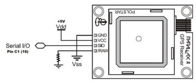
Image 1 shows the connection between the PIC and GPS Receiver Module.
Note that the pin labeled "Raw" needs to be grounded with a 1K resistor. The serial line also needs to be pulled high with a 1K resistor.
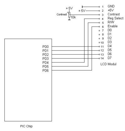
Image 2 shows the connection between the PIC and LCD.
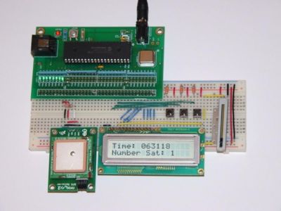
Image 3 is an example of how to wire all these elements together on one breadboard
Code
Include headers and set serial rate to 4800 baud
  #include <18F4520.h>
  #fuses HS,NOWDT,PUT,NOLVP
  #use delay(clock=20000000)
  #use rs232(baud=4800, rcv=PIN_C1)        //can use any pin to read from GPS, but define it here
  #include "flex_lcd.c"                    //included to allow easy writing to a parallel LCD display
Variable declarations and start of main loop
  char letter[300];
  int go = 0,wait = 0,commacount = 0,dataoutput = 1,j = 0;
  int16 i;
  int16 comma[90];

  void main()
  {
     lcd_init();
     while(TRUE)
     {
One of the most important aspects of this code is waiting for signal to return to high. Without this section, the rs232 command could end up in the middle of the output of the GPS and render all information unusable. This loop waits for the signal to remain high for over 2 bytes to ensure it is at the stop position before beginning to read.
        for (wait=0;wait<20;)               //for loop used to wait until signal has reset.  20*50us=1ms>two bytes of ones at 4800 baud
        {
           if (input(PIN_C1)==1)
           {
              wait++;
           }
           else if (input(pin_c1)==0)
           {
              wait = 0;
           }
           delay_us(50);
        }
After getting into the data loop, all data is recorded into a 300 character matrix letter
        for(i=0;i<300;i++)                  //record 300 characters into letter matrix
        {
           letter[i]= getc();
        }
The data is then parsed into sets of commas.
        for(i=0;i<300;i++)                  //parse matrix for commas (ascii=44 for a comma)
        {
           if (letter[i] == 44)
           {
              comma[commacount] = i;
              commacount++;
           }
        }
Counting variables are reset to zero at the end of the while loop
        go = 0;                             //reset testing variables back to zero
        commacount=0;
To finish the program, data must be converted into a usable format and output to the LCD screen. See full code above for an example of how to do this.


