Simulating circuits
Many software packages and online tools can simulate the behavior of circuits. Here we summarize LTspice, a free download for MacOS and Windows from Analog Devices. If the link breaks, just search "LTspice."
The Windows interface is fairly intuitive to use, while the MacOS interface is not. Below is a brief tutorial to get you started on the Mac; it should be easy to replicate these steps on Windows. You can also find video tutorials online, from Analog Devices and other sources.
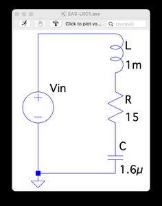
Below is an example circuit and the output of the simulation. At the bottom of this page, you can download some sample circuits to test.
Drawing Your Schematic
Reminder: the instructions below are for a Mac, which has an unintuitive interface. (The steps should be easy to replicate on Windows.) The instructions refer to "ctl-click" and "two-finger click." "ctl-click" means pressing the control button then clicking, and "two-finger click" (or "right click") means to use click with two fingers simultaneously.
We will create a circuit with a resistor, a capacitor, an inductor, and a variable voltage source.
- Create a new schematic. Choose File > New > New Schematic to create a new schematic window.
- Add a 10 Ohm resistor to the schematic. In the window, ctl-click > Draft > Component, click "res" in the pop-up window, and choose OK. Then your mouse will have a resistor attached to it. Click anywhere in the schematic window and a resistor will be placed there. After placing the resistor, the interface is ready for you to place another resistor, but we only want one, so press ESC to stop adding resistors. To set the resistance of the resistor, two-finger click on the resistor itself, or the text "R" next to the resistor, and in the pop-up window, change the value to 10. (If you wanted 1 milliOhm, you would type 1m. If you wanted 1.1 kiloOhm, you would type 1.1K or 1100. If you wanted 3.3 megaOhm, you would type 3.3M or 3300000.) The resistor is labeled R1. Since we will only have one resistor in the schematic, let's change the label to R. Two-finger click on the text R1 and change the label to R in the pop-up window.
- Add a 10 uF (microFarad) capacitor to the schematic. ctl-click > Draft > Component, click "cap" in the pop-up window, and choose OK. Put the capacitor anywhere; don't worry about connecting it orienting it yet. Change the value to "10u" (easier than typing 0.00001; you could use n for nanoFarad or p for picoFarad) and the label to "C" similar to what you did for the resistor.
- Add a 5 mH (milliHenry) inductor to the schematic. ctl-click > Draft > Component, click "ind" in the pop-up window, and choose OK. Change the value to "5m" and the label to "L."
- Add a variable voltage source to the schematic. ctl-click > Draft > Component, click "voltage" in the pop-up window, and choose OK. Change the label to "Vin." Two-finger click the voltage source to set its behavior. Choose "Advanced" from the pop-up window so we can get a behavior other than just a constant DC value. From the new pop-up window, choose the time domain function style "PULSE." This will make a periodic square-wave voltage that switches between "Vinitial" and "Von." The time the voltage is "on" is "Ton" and the period of the cycle is "Tperiod." You also need to set (DO WE HAVE TO SET TRISE AND TFALL, OR DOES IT DEFAULT TO GOOD VALUES? MENTION ALSO NCYCLES. DON'T MAKE THIS INFO VISIBLE ON THE SCHEMATIC, AND OTHERS YOU COULD EXPERIMENT WITH ARE SINE AND PWL PIECEWISE LINEAR). Finally, uncheck the "Make this information visible on the schematic" checkbox so the schematic is not so cluttered with text. (If the text is still there, edit something about the voltage and uncheck the box again, and the text should go away.)
- Add a ground symbol. You need this for every circuit to properly simulate. Press 'g' on your keyboard and your mouse will drag around a ground symbol that you can place by clicking. Press ESC to stop adding ground symbols.
- Move your components and connect everything together.
- To delete a component, ctl-click > Edit > Delete. This will create a scissors cursor. Click on the component and it will be deleted. ESC to exit the delete mode.
- To move a component, ctl-click > Edit > Move. Then use the mouse to select a component by click-dragging a box around it. The component will now be attached to your cursor and you can click anywhere to put it down. To rotate a component, press ctl-R. ESC to exit the move mode.
- Once your components are where you want them to be, connect them up with wires. ctl-click > Draft > Wires, click on a component endpoint, move the mouse to start drawing the wire, click when you want to make a turn, and click on another component endpoint to finish the connection. You can keep drawing wires by clicking on another component endpoint. ESC to edit the wire mode. You can delete a wire using the delete mode above. Make sure to connect your ground.
- Optional: Once your circuit looks the way you want it to, you can do ctl-click > View > Zoom to Fit to make your circuit fill your schematic window. You could also try ctl-click > View > Grid Dots if you want to see the drawing grid.
Your circuit should now look similar to the image below.
Running a Simulation
Try Some Sample Circuits
Download sample circuits to test.
