Sensor Overview
Below is a a brief overview of some common sensors for mechatronics. Many of these sensors produce analog voltages. If these voltages are to be read in by the ADC of a microcontroller, the voltage range may need to be boosted in electronics so that we get a good resolution signal. For example, if the analog voltage range of an output of a sensor is between 1.0 V and 1.1 V, for a PIC32 with a 10-bit ADC reading voltages between 0 and 3.3 V, we have only (0.1/3.3)*1024 = 31 different voltage values we can read in. If we assume the maximum of 1 bit of error in the ADC conversion, we are down to 16 different voltages that can be distinguished. This is a pretty significant quantization of the analog value.
To boost the signal to use most or all of the 0.0 to 3.3 V range, we can use an instrumentation amp or op amp circuit. If we want to power the op amp itself with 3.3 V and GND, we will need to use a special op amp that can achieve output voltages near the "rails" of 0 and 3.3 V. Many op amps cannot get within 1 or 1.5 V of their rails, which would make them pretty useless if powered with 3.3 V. So we must (1) choose an op amp that can go to the rails (these are typically more expensive than op amps that don't) and (2) design our op amp circuit to work from a single supply voltage (e.g., 3.3 V), as opposed to dual supply voltages (e.g., +/- 12 V). In other words, we can use no "negative" voltages. This is called "single supply design." You can see this page for some links on single supply design.
The sensors below are listed according to the quantities they measure. We could instead have chosen to list them according to the physical effect the use to transduce the quantity of interest into an electronic signal (typically voltage) that can be interpreted by a subsequent electronic circuit or microcontroller. More details on many of these sensors can be found under the Sensors page. You can also find lots of sensors useful for mechatronics projects at [Sparkfun].
Contact
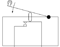
Mechanical buttons and switches are the simplest kinds of sensors. There are many types of switches. Momentary switches are ones that either establish a contact (normally open, or NO) or break a contact (normally closed, or NC), when a button is pressed. A "limit switch" is a particular type of NO momentary switch, shown at right. Limit switches, as shown at right, are often equipped with levers and are used to determine when some joint has reached the allowable limit of its motion.
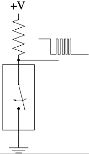
A typical configuration of a switch is shown at right. The pull-up resistor keeps the signal at +V until the switch closes, sending the signal to ground. As the switch closes, however, a series of micro-impacts may lead to “bounce” in the signal. A “debouncing” circuit may be necessary to clean up the output signal, to avoid counting multiple switch events. See, for example Switch Debouncing.
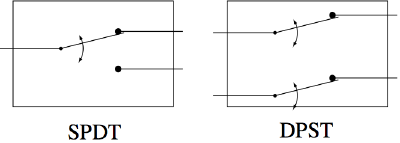
A switch may also have multiple poles (P) and one or two throws (T) for each pole. A pole moves as the switch is activated, and the throws are the possible contact points for the pole. Thus an SPDT (single pole double throw) switch switches a single pole from contact with one throw to the other, and a DPST (double pole single throw) switch switches two poles from open to closed circuit.
Linear and Angular Displacement
Potentiometers and encoders can be found in linear or angular variants.
Potentiometers
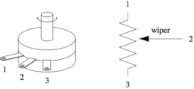
A potentiometer (or "pot") is a resistor with three connections: one at either end of the resistor, connected to two different voltage references (e.g., +V and GND); and a third connection to the "wiper" of the pot. This is a mechanical slider that moves over the resistor, creating a voltage divider. If the pot is 10 K, and the wiper is located at a position 70% of its travel, then 7 K of the pot is "above" the wiper and 3 K of the pot is "below" the wiper. This makes an inexpensive and easy-to-use linear and angular sensor, and can be used for things like user-input sliders (e.g., stereo equalizers) or sensing the angle of a robot joint. Some more information can be found here.
Encoders
Encoders convert linear and rotational motions to a bit code (absolute encoders) or a pulse train (the much-more-common incremental encoders). More information can be found here.
Flex (Bend) Sensors
A flex sensor is a resistor printed on a flexible surface. When the surface bends one way or another, the resistance changes.
Ultrasonic Sensors
Ultrasonic sensors generate an ultrasonic pulse and then use time-of-flight of the return of the pulse to an ultrasonic microphone to determine the approximate distance to an object in the environment. The pulses are not focused, Learn more here.
Light
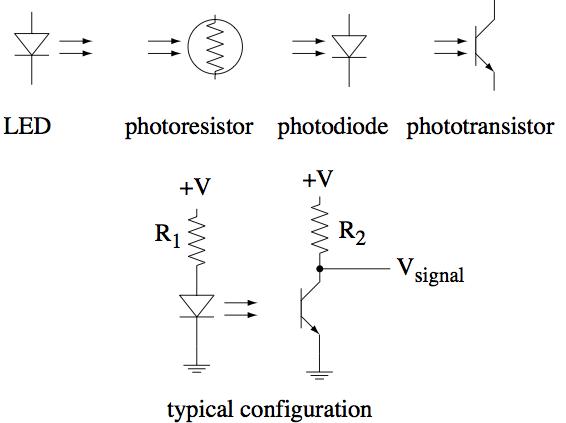
Light sensors can be used to measure many different physical quantities. A photocell is a resistor with a resistance that varies based on the amount of light hitting it. A photodiode creates a reverse current when light of the right wavelengths hits it. The current is typically very small (e.g., uA), but the response time is fast (ns). A phototransistor, on the other hand, typically creates larger currents (e.g., mA) but with a slower response time (us). The light acts as the base current, creating a collector current.
Photodiodes and phototransistors are commonly used with LEDs as light sources. We can then sense whether the LED and photodiode/transistor can "see" each other or are blocked (and this is the basis for most encoder designs), or how far they are from each other (e.g., to measure the distance to an external surface which bounces outgoing LED light back to the detector). When the LED and phototransistor are packaged together in a single package, they are called optointerrupters, and optoreflectors, respectively.
You can learn more about photocells and photodiodes and phototransistors.
Magnetic Field
Hall Effect Sensors
Hall effect sensors generate a voltage in the presence of a magnetic field. This effect can be used for digital switches or for analog sensing. More information can be found here.
Reed Switches
Reed switches are normally open, but will close in the presence of a magnetic field. See
Reed Switch for more information.
Acceleration
Acceleration in 1-3 directions can be measured by MEMS accelerometers. See here for more details.
Velocity
Tachometers
A tachometer uses the same principle that DC motors and hydroelectric dams rely on: when a coil of wire is rotated in a magnetic field, a voltage is generated across the ends of the coil that is proportional to the speed of rotation and the strength of the magnetic field. This can be used to make an angular velocity (e.g, RPM) sensor. Since a DC motor works on the same principle, you can spin the motor shaft (e.g., by hand) and measure the voltage at the two terminals of the motor.
Gyros
Modern inexpensive angular rate gyroscopes are based on MEMS technology and are used to measure the angular rate of rotation in one or more axes. You can find a variety of MEMS gyroscopes at [Sparkfun].
Force
Strain Gauges
Strain gauges are resistors that are bonded to a surface and change their resistance as the surface stretches or compresses. The surface is typically stiff (metal) and the stretch/compression is tiny. These are treated as force sensors because the displacement is small but the forces may be large, due to the stiffness of the underlying material. See Strain Gauge for more information.
You can also get "load cell" or "force/torque" sensors that package a number of strain gauges into a single device and return the six-dimensional force and torque applied to one end relative to a grounded end. These tend to be quite expensive due to high precision manufacturing and calibration.
Force-Sensitive Resistors
A force-sensitive resistor changes resistance with force. See this page to learn more.
Temperature
Temperature can be measured by thermistors, thermocouples, and even diodes. The forward bias voltage of a diode typically varies rather linearly from the nominal 0.6 V to 0.7 V as a function of temperature. For example, the forward bias voltage may be 0.7 V at 20 deg C but 0.5 V at 100 deg C. By measuring the voltage across the diode, we can estimate the temperature. To get a larger voltage swing, we can put several diodes in series.
Sound
See, for example, the Microphones page.
Current
A current sensor can be as simple as a resistor across which you measure the voltage. Typically you want this resistor to be low resistance so as to have little effect on your circuit, such as 0.1 or 0.01 ohms, or even less. This typically means low voltage drop, too, so the voltage may need to be amplified by an op amp or instrumentation amp. Integrated circuit (IC) chips are also available that do this for you, turning the current into a voltage or even a PWM signal.
