Accessing Pinion of Globe Motor
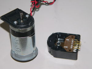
The Globe motor we have in stock can be modified to be high speed and low torque with a few adjustments.
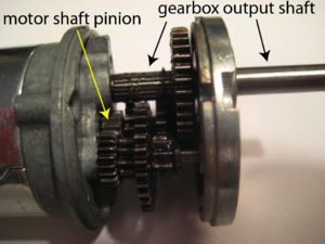
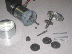
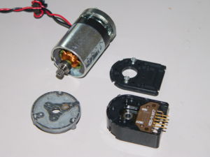
It is easy to do until the disassembled photo below. Simply unscrew the three long screws and pull off the top of the gearbox, along with the output shaft of the gearbox. Now you can see two shafts holding the stacks of gears actually implementing the reduction ratio. Using a pair of pliers, pull off the spacers near the tops of these shafts (these are press-fitted onto the shafts). Now the gears slide off the shafts. (Actually, when I tried it, one shaft came out with the spacer, while the other shaft remained in place and only the spacer came off.) The photo below shows the new state of the gearbox. Be careful not to manhandle the encoder when you apply large forces pulling off the spacers! You could damage the encoder.
The rest of the gearbox is held in place by two long screws that run the full length from the back of the motor. These screws cannot be removed without removing the encoder. Therefore, if you want to better expose the motor's output shaft without entirely disassembling the motor, you can use a band saw to cut off the nearby posts (or to cut off the entire gearhead from the lip up) and to destroy and remove the pinion gear on the motor output shaft.
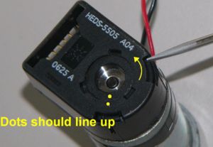
The more involved but safer method to access the pinion or output shaft is to disassemble to motor. To do this, use a small screwdriver to rotate the internal mechanism in the encoder. See the picture below.
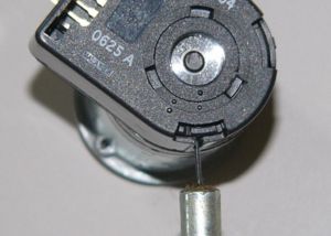
Rotate this as far as it will go until the one dot lines up with the one dot on the outside of the encoder. This will line up a slot of the side of the encoder which a 0.035" hex wrench can be inserted into. While applying a bit of pressure to the wrench, turn the pinion until the hex wrench fits into a set screw. Unscrew this set screw a couple of turns and then pull gently on the encoder. This will get to the following image:
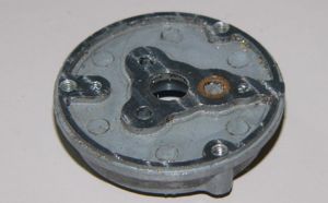
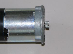
Now unscrew the two exposed screws and then you will have access to the two bolts holding the motor together. Unscrew these and the top portion of the motor can now be removed. The best way to expose the pinion is to mill the top section of the motor to be much lower. See the following photos for results. Assemble the motor in reverse order, ensuring the set screw is tightened sufficiently.
