Difference between revisions of "Rotational Stiffness"
EricNickel (talk | contribs) (→Torque) |
EricNickel (talk | contribs) |
||
| Line 154: | Line 154: | ||
===Rotational Stiffness=== |
===Rotational Stiffness=== |
||
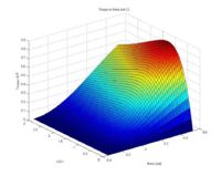
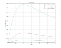
The rotational stiffness is the change in torque required to achieve a change in angle. Taken as a differential quantity, it is dT/d(theta). As the plots above show, the effect of changing angle on torque for a given L2 distance is approximately linear, therefore we assume a linear stiffness. This produces the following relationship for the joint: |
|||
T = k(rotational) * (theta + pi/9) |
|||
The spring is neutral at an angle of -pi/9, hence the constant in the above equation. |
|||
<br clear=all> |
<br clear=all> |
||
Revision as of 22:34, 20 March 2008
Stiffness
Stiffness (k) is the relationship between an applied force and the displacement the force produces. This relationship can be defined for two common cases:
In the linear case, the applied force (F) is proportional to the linear displacement (x) of one end of the "spring" with respect to the other (i.e. the amount of stretch or compression of the spring).
F = k * x
In the rotational case, the applied torque (T) is proportional to the angular displacement (theta) of one side/end with respect to the other.
T = k * theta
In both cases, the relationship can be non-linear, however a linear relationship is easier to work with.
Linear Spring
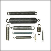
A linear extension spring is generally a coil, usually made of a tempered steel. The thickness of the wire used to make the spring and the number and diameter of the coils determines the stiffness. Over the elastic extension range for the spring, the relationship between the extension of the spring and the force required to attain that extension is linear. This type of spring obeys Hook's Law:
F = k * x
Torque/Moment
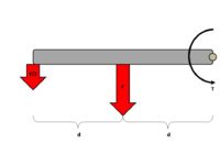
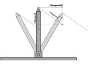
A torque (T), or moment, is the product of the force (F) applied tangentially to the rotation of an object (i.e. perpendicular to the axis ALONG the rotating member) and the distance (d) between the axis of rotation and the location of the applied force. In short, this amounts to the effect of a lever. A longer "arm" increases the torque provided by a given force. In converse, for a constant torque, the force produced is inversely related to the distance, so at twice the distance the force is halved. This is shown in the figure at right, and the relationship is given by the formula:
T = F * d
Vector Decomposition
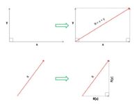
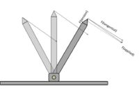
The sum of two vectors can be described by a single vector (the resultant). At right is a figure which shows how two vectors can be summed to produce a resultant, and how a single vector can be reduced to two orthogonal components.
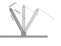
Applying this vector decomposition to the forces applied to a rotating member, it is possible to decompose an applied force to two components:
- The axial component is the force directed along the long axis of the rotating member. This force is a compressive force.
- The tangential component is the force directed perpendicular to the long axis of the rotating member. This force produces a torque or moment about the axis of rotation.
In the programmable stiffness joint project, the angle between the spring and the rotating member is noted as beta, and therefore determines the proportion of the spring tension force which is applied to producing torque. It is also important to note that in the device, the orientation of the applied force changes with the angle of the rotating member as well, so the change is not as dramatic as shown in the images at right which have constant applied force orientation.
Programmable Stiffness Joint
Static Insertion
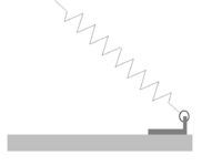
The static insertion point is at a set distance (L1) from the axis of rotation. The spring end loop is hooked through a bracket affixed to the base plate, providing a direct physical connection between the spring and the base plate.
Rotating Insertion
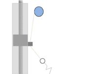
The rotating insertion point is located on a slider which moves in a track. A threaded rod rotates, causing the slider to move in either direction along the length of the rotating member. The slider has a hole though which passes a length of wire or cable. This is to account for the change in distance between the two insertion points allowing for a constant length spring at the set-point angle. The fishing line we used can stretch to some degree, so this is not the optimal solution, but a better cable would not stretch as much.
Spring Extension
The spring is placed into a reference state (constant tension) at an angle of theta = -20 degrees. At that angle the spooling motor is driven to stall, so the tension on the fishing line (and therefore the spring) is set to a known value. Using pulse width modulation, it is easy to make that initial pre-tension relatively low. Physical stops prevent the device from having angles less than -20 degrees.
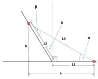
This pre-tensioning is done at the end of all changes to the position of the slider (adjusting the L2 distance) to remove the slack from the cable. So at the angle -20 degreese, the spring is at a constant tension for any L2 distance. As the shank rotates about the axis, the position of the mobile insertion point changes. The position components are called "h" and "a" where h is the height with respect to the base plate and a is the lateral position with respect to the axis of rotation (so a negative angle would have a negative a).
The distance between the static insertion point and the mobile insertion point is easy to obtain using the pythagorean theorem. The one leg is simply h, while the other is a = L1 + sin(theta). The distance between the insertion points is:
sqrt(h^2 + a^2)
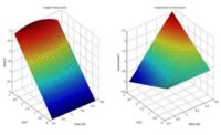
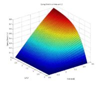
Subtracting the initial distance from each distance computed over the range of angles and L2 lengths produces the amount of extension the spring experiences as the angle changes and L2 changes. Correspondingly, the tension on the cable (and therefore applied to the mobile insertion point) is linearly related to the spring extension due to Hook's Law as described above.
Torque
The amount of tension applied to the rotating insertion point is directly proportional to the amount of extension of the spring as a result of Hook's Law. This is the force applied to the rotating member, and a force applied to an object a distance away from its axis of rotation produces a torque or moment.
F = k * x (Hook's Law)
T = F * d
Only the component of the tension force which is tangential to the rotation will produce a torque, so the angle of the tension force must also be computed. First, the positions of the two insertion points must be computed. The static insertion point is defined as the reference point, and the relative position of the rotating insertion point is computed.
h = L2 * cos(theta)
a = L1 + L2 * sin(theta)
With the location of the rotating insertion point defined, the angle between the spring and the base plate (alpha on the diagram at right) can be computed, and from that the angle between the spring and the rotating member (beta on the diagram at right). Since the sum of the angles of a triangle is 180 degrees (pi radians) for any triangle, knowing the angles alpha and theta we can calculate the angle beta.
alpha = arctan(h/a)
beta = pi/2 - (theta + alpha)
The resulting torque is the tangential component of the tension force multiplied by the distance between the axis of rotation and the point of application of the force (L2). The stretch of the spring is L3 - L3(initial) and the spring has a linear stiffness k.
F(tangential) = k * (L3 - L3(initial)) * sin(beta)
T = F(tangential) * L2
Rotational Stiffness
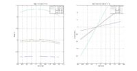
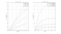
The rotational stiffness is the change in torque required to achieve a change in angle. Taken as a differential quantity, it is dT/d(theta). As the plots above show, the effect of changing angle on torque for a given L2 distance is approximately linear, therefore we assume a linear stiffness. This produces the following relationship for the joint:
T = k(rotational) * (theta + pi/9)
The spring is neutral at an angle of -pi/9, hence the constant in the above equation.
