Difference between revisions of "Capstone Dev"
| Line 127: | Line 127: | ||
* A 9-vector indicating the arm joint speeds (5 variables) and the wheel speeds (4 variables). |
* A 9-vector indicating the arm joint speeds (5 variables) and the wheel speeds (4 variables). |
||
* A timestep <math>\Delta t</math>. |
* A timestep <math>\Delta t</math>. |
||
* A positive real value indicating the maximum angular speed of the arm joints and the wheels. (For example, if this value is 7.3, the angular speed of the wheels and arm joints is limited to the range [-7.3 radians/s, 7.3 radians/s].) If you don't want speed limits, just use a very large number. If you prefer, your function can accept separate speed limits for the wheels and arm joints. |
|||
'''Output:''' |
'''Output:''' |
||
| Line 146: | Line 147: | ||
# . The robot chassis should rotate in place by 1 radian. |
# . The robot chassis should rotate in place by 1 radian. |
||
# . The robot should |
# . The robot should |
||
speed limit |
|||
=== Milestone 2: Reference Trajectory Generation === |
=== Milestone 2: Reference Trajectory Generation === |
||
Revision as of 11:46, 30 May 2018
This page describes the Capstone Project for the Coursera "Modern Robotics" Specialization. This project forms the sixth and final course of the Specialization: "Modern Robotics, Course 6: Capstone Project, Mobile Manipulation." This project draws on pieces of Courses 1 to 5.
A video summary of this project is given in this YouTube video.
Depending on your experience with programming, this project should take approximately 20 hours, broken down into three intermediate milestones and the final completed software plus demonstrations of it.
You should use the Modern Robotics code library to help you complete this project.
Introduction
In your capstone project, you will write software that plans a trajectory for the youBot mobile manipulator (a mobile base with four mecanum wheels and a 5R robot arm), performs odometry as the chassis moves, and performs feedback control as the youBot picks up a block at a specified location, carries it to a desired location, and puts it down.
The final output of your software will be a comma separated values (csv) text file that specifies the configurations of the chassis and the arm, the angles of the four wheels, and the state of the gripper (open or closed) as a function of time. This specification of the position-controlled youBot will then be "played" on the V-REP simulator to see if your trajectory succeeds in solving the task.
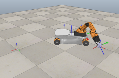
This project uses the CSV Mobile Manipulation youBot scene. You should download it and test it with the sample csv file, to see what a solution looks like.
Unlike previous projects, where we used V-REP to simply visualize the robot's motion, in this project V-REP will use a physics simulator to simulate the interaction of the youBot with the block. In other words, if the gripper closes on the block in the wrong position or orientation, the block may simply slide out of the grasp.
The V-REP scene drives the chassis configuration according to the sequence of chassis configurations in your csv file. For the robot arm, simulated high-gain controllers at the arm joints cause the arm to closely follow the configurations in your csv file.
The interaction between the robot and the block is governed by a physics simulator, often called a "physics engine," which approximately accounts for friction, mass, inertial, and other properties. V-REP has different physics engines which you can select, including Bullet and ODE.
The time between each successive configuration in your csv file is 0.01 seconds (10 milliseconds). A typical line of your csv file would be something like
-0.75959, -0.47352, 0.058167, 0.80405, -0.91639, -0.011436, 0.054333, 0.00535, 1.506, -1.3338, 1.5582, 1.6136, 0
i.e., thirteen values separated by commas, representing
chassis phi, chassis x, chassis y, J1, J2, J3, J4, J5, W1, W2, W3, W4, gripper state
where J1 to J5 are the arm joint angles and W1 to W4 are the four wheel angles.
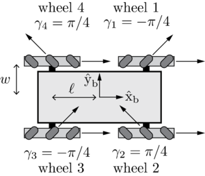
Wheels 1 to 4 are numbered as shown in the image to the right. The ten angles (phi for the chassis, five arm joint angles, and four wheel angles) are in radians and the two chassis position coordinates (x,y) are in meters. A gripper state of 0 indicates that you want the gripper to be open, and a gripper state of 1 indicates that you want the gripper to be closed. In practice, the transition from open to closed (or from closed to open) takes up to one second, so any transition from 0 to 1, or 1 to 0, in your csv file will take some time to complete.
Your software will take as input:
- the initial resting configuration of the cube object (which has a known geometry), represented by a frame attached to the center of the object
- the desired final resting configuration of the cube object
- the actual initial configuration of the youBot
- the reference initial configuration of the youBot (which will be different from the actual initial configuration, to allow you to test feedback control)
The output of your software will be a single csv file which, when "played" through the V-REP scene, should successfully pick up the block and put it down at the desired location.
Your solution must employ automated planning and control techniques from this Coursera specialization. It should not simply be a manually coded trajectory of the robot. Your solution should automatically go from the input to the output, with no other human intervention. In other words, it should automatically produce a working csv file even if the input conditions are changed.
In your software, you should first piece together a reference trajectory for the gripper of the robot, which the robot is then controlled to follow. A typical reference trajectory would consist of the following segments:
- A trajectory to move the gripper from its initial configuration to a "standoff" configuration a few cm above the block.
- A trajectory to move the gripper down to the grasp position.
- Closing of the gripper.
- A trajectory to move the gripper back up to the "standoff" configuration.
- A trajectory to move the gripper to a "standoff" configuration above the final configuration.
- A trajectory to move the gripper to the final configuration of the object.
- Opening of the gripper.
- A trajectory to move the gripper back to the "standoff" configuration.
Segments 3 and 7 each keep the end-effector fixed in space but, at the beginning of the segment, change the state of the gripper from 0 to 1 or 1 to 0, waiting one second for the gripper closing to complete. In other words, each of these segments would consist of 100 identical lines of the csv file (corresponding to one second), where the first line has a gripper state different from the previous line in the csv file, to initiate the opening or closing.
Segments 2, 4, 6, and 8 are simple up or down translations of the gripper of a fixed distance. Good trajectory segments would be cubic or quintic polynomials taking a reasonable amount of time (e.g., one second).
Trajectory segments 1 and 5 are longer motions requiring motion of the chassis. Segment 1 is calculated from the desired initial configuration of the gripper to the standoff configuration, and segment 5 is calculated from the first standoff configuration to the second standoff configuration. The gripper trajectories could correspond to constant screw motion paths or decoupled Cartesian straight-line motion plus rotational motion, time scaled by third-order polynomials (Chapter 9).
Once the entire gripper reference trajectory has been pieced together from the 8 segments, the actual trajectory of the youBot is obtained by using a Jacobian pseudoinverse position controller as described in Chapter 13.5. Starting from the actual initial robot configuration (which has some error from the beginning of reference segment 1), your controller drives the gripper to follow segment 1, so that the gripper is at the standoff configuration for the beginning of segment 2. Your feedback controller should eliminate initial error before the gripper attempts to grasp the block, to avoid failure.
You are welcome to adopt a different approach to solving the pick-and-place problem, provided your approach takes the same inputs specified above, produces a csv file that successfully achieves the task, and is fully automatic (i.e., it works for different initial and final configurations of the block, different initial and reference configurations for the youBot, and requires no human intervention).
To simulate the effect of feedback control, you must write your own motion simulator. For each timestep, you take the initial configuration of the robot and the wheel and joint speeds calculated by your controller and numerically integrate the effect of these speeds over a timestep to get the new robot configuration. To calculate the new configuration of the chassis due to the wheel motions, you must implement an odometry step (Chapter 13.4).
Kinematics of the youBot
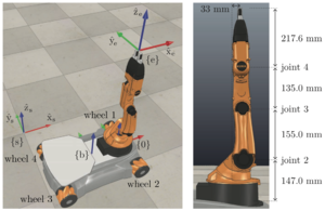
The images to the right illustrate the youBot. Click on them to make them bigger. The description below is consistent with Exercise 13.33 from the book, if you prefer to see the information there. All distances are in meters and all angles are in radians.
The configuration of the frame {b} of the mobile base, relative to the frame {s} on the floor, is described by the 3-vector or the matrix
where meters is the height of the {b} frame above the floor. The forward-backward distance between the wheels is meters and the side-to-side distance between wheels is meters. The radius of each wheel is meters. The forward driving and "free sliding" direction of each wheel is indicated in the figures.
The fixed offset from the chassis frame {b} to the base frame of the arm {0} is
When the arm is at its home configuration (all joint angles zero, as shown in the figure), the end-effector frame {e} relative to the arm base frame {0} is
When the arm is at its home configuration, the screw axes for the five joints are expressed in the end-effector frame {e} as
In this project, for simplicity we assume no joint limits on the five joints of the robot arm. It is recommended, however, that you choose limits on the wheel and joint velocities. We will come back to this issue later.
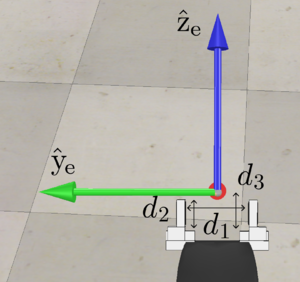
The end-effector frame {e} is rigidly attached to the last link and is midway between the tips of the gripper fingers. The minimum opening distance of the gripper is cm, the maximum opening distance is cm, the interior length of the fingers is cm, and the distance from the base of the fingers to the frame {e} is cm. When the gripper closes, it closes until it reaches its minimum closing distance or encounters a force large enough to prevent further closing.
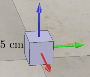
The object being manipulated is a cube, 5 cm x 5 cm x 5 cm. The cube's frame {c} is at the center of the cube, and the axes are aligned with the edges of the cube. The initial configuration of the cube is at (x, y, z) = (1, 0, 0.025 ) m in the space frame {s}, and the axes of {c} are aligned with {s}. The desired final configuration of the cube is at (x, y, z) = (0, 1, 0.025) m and the axes of {c} are rotated by about the axis of {s}. A good choice for the "standoff" configuration before moving down to the cube and moving back up (the ends of trajectories 1, 4, 5, and 8) is to have the {e} frame a few cm above the {c} frame.
What You Will Do
Your solution to this project will be a fairly complex piece of software. To help structure the project, and to allow you to test individual pieces of your solution, the project has three milestones before you finally complete the project. You do not turn in your solutions to these milestone subprojects; you only turn in your final project.
Then more details on milestones, and the actual geometry, configurations, initial and final conditions, etc., for the demonstrator.
Milestone 1: youBot Kinematics Simulator and csv Output
You will write a simulator for the kinematics of the youBot. The central function, let's call it nextState, is specified by the following inputs and outputs:
Input:
- A 12-vector representing the current configuration of the robot (3 variables for the chassis configuration, 5 variables for the arm configuration, and 4 variables for the wheel angles).
- A 9-vector indicating the arm joint speeds (5 variables) and the wheel speeds (4 variables).
- A timestep .
- A positive real value indicating the maximum angular speed of the arm joints and the wheels. (For example, if this value is 7.3, the angular speed of the wheels and arm joints is limited to the range [-7.3 radians/s, 7.3 radians/s].) If you don't want speed limits, just use a very large number. If you prefer, your function can accept separate speed limits for the wheels and arm joints.
Output:
- A 12-vector representing the configuration of the robot time later.
Your simulator should be a simple first-order Euler simulation, i.e.,
- new arm joint angles = (old arm joint angles) + (joint speeds) *
- new wheel angles = (old wheel angles) + (wheel speeds) *
The new chassis configuration is obtained from odometry, as described in Chapter 13.4.
To test your function nextState, and to test your ability to produce a csv file that can be read
now iterate and write a csv file
To test your solution: Once you have written the function above, you should test your odometry by driving the robot for 1 second with the following wheel speeds:
- . The robot chassis should drive forward (in the Failed to parse (syntax error): {\displaystyle +\hat{\text{x|}_{\text{b}}} direction by 1 meter.
- . The robot should slide
- . The robot chassis should rotate in place by 1 radian.
- . The robot should
speed limit
Milestone 2: Reference Trajectory Generation
Frequencies: control, reference trajectory, images for animation, numerical integration (but since no state dependence in eqs of motion, no need for this)
Milestone 3: Feedforward Control
control can happen at a higher frequency than reference, and simulation
Completed Project and Your Submission
What to turn in: some more text
- stuff 1
- stuff 2
etc.
Project grading.





![{\displaystyle T_{sb}(q)=\left[{\begin{array}{cccc}\cos \phi &-\sin \phi &0&x\\\sin \phi &\cos \phi &0&y\\0&0&1&0.0963\\0&0&0&1\end{array}}\right]}](https://wikimedia.org/api/rest_v1/media/math/render/svg/b47257eb7970f48760d2e63f234ada12b6c2b441)

![{\displaystyle T_{b0}=\left[{\begin{array}{cccc}1&0&0&0.1662\\0&1&0&0\\0&0&1&0.0026\\0&0&0&1\end{array}}\right].}](https://wikimedia.org/api/rest_v1/media/math/render/svg/1b10156ace98a292244209f583368c4de8f50942)
![{\displaystyle M_{0e}=\left[{\begin{array}{cccc}1&0&0&0.033\\0&1&0&0\\0&0&1&0.6546\\0&0&0&1\end{array}}\right].}](https://wikimedia.org/api/rest_v1/media/math/render/svg/9c9e700700bbd505a17718ed8e8e5499e6208a54)


