Difference between revisions of "NU32"
MatthewElwin (talk | contribs) |
|||
| Line 54: | Line 54: | ||
== The NU32 == |
== The NU32 == |
||
=== Ordering === |
|||
The NU32 boards are currently in production and will be available late December. If you are interested in purchasing, visit [[http://goo.gl/forms/GkgjRLE0NR Notification Form]] to register and receive a notification |
|||
when the boards are ready for purchase. |
|||
=== Technical Specifications === |
|||
[[File:NU32_pinout.jpg|x200px|thumb|right|The pinout of the NU32 board.]] |
[[File:NU32_pinout.jpg|x200px|thumb|right|The pinout of the NU32 board.]] |
||
Revision as of 14:10, 9 December 2015
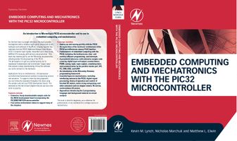
Home page of the NU32 PIC32 development board and the book "Embedded Computing and Mechatronics with the PIC32 Microcontroller" (Amazon, Elsevier), by Kevin M. Lynch, Nicholas Marchuk, and Matthew L. Elwin (Newnes/Elsevier, December 2015).
From the back cover:
For the first time in a single reference, this book provides the beginner with a coherent and logical introduction to the hardware and software of the PIC32, bringing together key materials from the PIC32 Reference Manual, Data Sheets, XC32 C Compiler User's Guide, Assembler and Linker Guide, MIPS32 CPU manuals, and Harmony documentation. This book also teaches you to use the Microchip documentation, allowing better life-long learning of the PIC32. The philosophy is to get you started quickly, but to emphasize fundamentals and to eliminate "magic steps" that prevent a deep understanding of how the software you write connects to the hardware.
Applications focus on mechatronics: microprocessor-controlled electromechanical systems incorporating sensors and actuators. To support a learn-by-doing approach, you can follow the examples throughout the book using the sample code and your PIC32 development board. The exercises at the end of each chapter help you put your new skills to practice.
Features include:
- Extensive, freely downloadable sample code for the NU32 development board incorporating the PIC32MX795F512H microcontroller
- Free online instructional videos to support many of the chapters
Coverage includes:
- Getting up and running quickly with the PIC32
- An exploration of the hardware architecture of the PIC32 and differences between PIC32 families
- Fundamentals of embedded computing with the PIC32, including the build process, time- and memory-efficient programming, and interrupts
- A peripheral reference, with extensive sample code covering digital input and output, counter/timers, PWM, analog input, input capture, watchdog timer, and communication by the parallel master port, SPI, I2C, CAN, USB, and UART
- An introduction to the Microchip Harmony programming framework
- Essential topics in mechatronics, including interfacing sensors to the PIC32, digital signal processing, theory of operation and control of brushed DC motors, motor sizing and gearing, and other actuators such as stepper motors, RC servos, and brushless DC motors
- Appendices introducing the C programming language and background material on circuit analysis
This book is ideal for beginners, as a reference for professionals, or as a textbook for a college course on mechatronics.
Sample Chapters
The freely downloadable sample chapters include:
- the Table of Contents
- the Preface
- Chapter 1: Quickstart (getting up and running with the NU32 quickly)
- Chapter 2: Hardware (description of the PIC32 architecture, memory map, pins, peripherals, and special function registers, as well as the NU32 development board)
- Chapter 25: Brushed Permanent Magnet DC Motors (motor physics, speed-torque curve, and DC motor data sheets)
- Appendix A: A Crash Course in C
- Appendix B: Circuits Review
- Appendix C: Other PIC32 Models
Book Source Code
Full source code from the book (November 2015)
Just the Quickstart Code, as needed for Chapter 1: PIC32Quickstart.zip (November 2015)
Videos
Videos to support several of the book chapters are posted here.
The NU32
Ordering
The NU32 boards are currently in production and will be available late December. If you are interested in purchasing, visit [Notification Form] to register and receive a notification when the boards are ready for purchase.
Technical Specifications
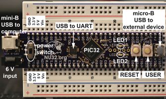
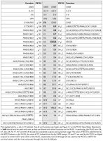
A photo of the NU32 development board is shown at the top of the page, and the pinout is given in the image to the right. The NU32 board provides easy breadboard access to most of the PIC32MX795F512H's 64 pins. The NU32 acts like a big 60-pin DIP (dual in-line package) chip and plugs into a standard prototyping breadboard.
Beyond simply breaking out the pins, the NU32 provides many features that make it easy to get started with the PIC32. For example, to power the PIC32, the NU32 provides a barrel jack that accepts a 1.35 mm inner diameter, 3.5 mm outer diameter center-positive power plug. The plug should provide 1 A at DC 6 V or more. The PIC32 requires a supply voltage VDD between 2.3 and 3.6 V, and the NU32 provides a 3.3 V voltage regulator providing a stable voltage source for the PIC32 and other electronics on board. Since it is often convenient to have a 5 V supply available, the NU32 also has a 5 V regulator. The power plug's raw input voltage Vin and ground, as well as the regulated 3.3 V and 5 V supplies, are made available to the user as shown in the photo at the top of the page and in the pinout. The power jack is directly connected to the Vin and GND pins so you could power the NU32 by putting Vin and GND on these pins directly and not connecting the power jack.
The 3.3 V regulator provides up to 800 mA and the 5 V regulator provides up to 1 A of current, provided the power supply can source that much current. In practice you should stay well under each of these limits. For example, you should not plan to draw more than 200 to 300 mA or so from the NU32. Even if you use a higher-current power supply, such as a battery, you should respect these limits, as the current has to flow through the relatively thin traces of the PCB. It is also not recommended to use high voltage supplies greater than 9 V or so, as the regulators will heat up.
Since motors tend to draw lots of current (even small motors may draw hundreds of milliamps up to several amps), do not try to power them from the NU32. Use a separate battery or power supply instead.
In addition to the voltage regulators, the NU32 provides an 8 MHz resonator as the source of the PIC32's 80 MHz clock signal. It also has a mini-B USB jack to connect your computer's USB port to a USB-to-UART FTDI chip that allows your PIC32 to use its UART to communicate with your computer.
A USB micro-B jack is provided to allow the PIC32 to speak USB to another external device, like a smartphone.
The NU32 board also has a power switch which connects or disconnect the input power supply to the voltage regulators, and two LEDs and two buttons (labeled USER and RESET) allowing very simple input and output. The two LEDs, LED1 and LED2, are connected at one end by a resistor to 3.3 V and the other end to digital outputs RF0 and RF1, respectively, so that they are off when those outputs are high and on when they are low. The USER and RESET buttons are attached to the digital input RD7 and MCLR pins, respectively, and both buttons are configured to give 0 V to these inputs when pressed and 3.3 V otherwise.
Because pins RG6 through RG9, RF0, RF1, and RD7 on the PIC32 are used for UART communication with the host computer, LEDs, and the USER button, other potential functions of these pins are not available if you would like to use the communication, LEDs, and USER button. In particular:
- UART6 is unavailable (conflicts with pins RG6 and RG9). Since UART3 is used for communication with the host computer, this leaves UART1, UART2, UART4, and UART5 for your programs.
- SPI2 is unavailable (conflicts with pins RG6 and RG7). This leaves SPI3 and SPI4.
- I2C4 is unavailable (conflicts with pins RG7 and RG8). This leaves I2C1, I2C3, and I2C5.
- The default CAN1 pins C1RX and C1TX cannot be used (they conflict with pins RF0 and RF1), but the configuration bit FCANIO in DEVCFG3 has been cleared to zero on the NU32, thereby setting CAN1 to use the alternate pins AC1RX (RF4) and AC1TX (RF5). Therefore no CAN module is lost.
- MII ethernet is unavailable (conflicts with pins RD7, RF0, and RF1). The PIC32 can implement ethernet communication using either the media-independent interface (MII) or the reduced media-independent interface (RMII), and RMII ethernet communication, which uses many fewer pins than MII, is still available on the NU32.
- Several change notification and digital I/O pins are unavailable, but many more remain.
In all, very little functionality is unavailable due to connections on the NU32, and advanced users can find ways to bypass even these limitations.
If for some reason you do not want to use the bootloader that comes pre-installed on the NU32, you can program the PIC32 using an external programming device like the PICkit 3, as shown in the image on the right. Simply use header pins in the PICkit 3 connector to lean against the plated holes on the NU32, as shown. Your software must set the configuration bits, and you will likely overwrite the pre-installed bootloader. You can also use an external programmer to install a new bootloader.
Other: Where to buy, parts list, schematic, Gerber file, bootloader, powering the NU32 from your USB port, etc.
Book Errata
Corrections to the book will be provided here.
Data Sheets
Data sheets for several of the ICs used in the book.
About the Authors
Kevin Lynch received his BSE in Electrical Engineering from Princeton University and his PhD in Robotics from Carnegie Mellon University, and he is currently Professor and Chair of the Mechanical Engineering Department at Northwestern University. He has been teaching mechatronics at Northwestern for over 15 years, and he has been awarded Northwestern’s highest teaching awards. He publishes and lectures widely on his research in robotics. He is a Fellow of the IEEE.
Nick Marchuk is a Lecturer in Mechatronics and directs the Mechatronics Design Lab at Northwestern University. He teaches introductory and advanced courses in mechatronics and directs student projects in electromechanical design. He received his BS degree in Mechanical Engineering from Johns Hopkins University and his MS in Mechanical Engineering from Northwestern.
Matthew Elwin is currently a PhD candidate in Mechanical Engineering at Northwestern University, where he has served as a teaching assistant for its mechatronics course. He earned BA and BE degrees in engineering sciences from Dartmouth College in 2009 and his MS in Mechanical Engineering from Northwestern in 2013. His research is in swarm robotics.


