Difference between revisions of "NU32v2: What is in the NU32v2 Kit"
From Mech
Jump to navigationJump to searchNickMarchuk (talk | contribs) |
NickMarchuk (talk | contribs) |
||
| Line 13: | Line 13: | ||
<td>[[Image:nu32v2_breakoutbreadboardsswitch.jpg|thumb|200px|The NU32v2|center]]</td> |
<td>[[Image:nu32v2_breakoutbreadboardsswitch.jpg|thumb|200px|The NU32v2|center]]</td> |
||
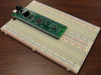
<td>NU32v2 in 2 breadboards with a switch between GND and the G6 pin</td> |
<td>NU32v2 in 2 breadboards with a switch between GND and the G6 pin</td> |
||
<td>[[http://hades.mech.northwestern.edu/index.php/NU32v2:_Software_to_Install]], [[http://hades.mech.northwestern.edu/index.php/NU32v2:_Starting_a_New_Project_and_Putting_it_on_the_NU32v2 |
<td>[[http://hades.mech.northwestern.edu/index.php/NU32v2:_Software_to_Install Software to Install]], [[http://hades.mech.northwestern.edu/index.php/NU32v2:_Starting_a_New_Project_and_Putting_it_on_the_NU32v2]]</td> |
||
</tr> |
</tr> |
||
Revision as of 14:30, 16 January 2011
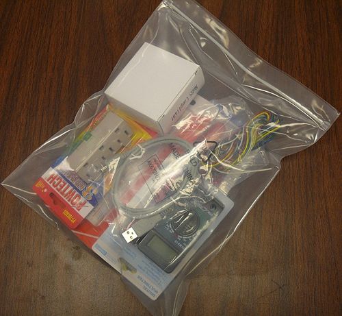
The NU32v2 kit contains everything necessary to begin programming the NU32v2 board. Check to make sure your bag contains all of the items listed below. Components in the kit:
| Picture | Description | Link |
|---|---|---|
| NU32v2 in 2 breadboards with a switch between GND and the G6 pin | [Software to Install], [[1]] | |
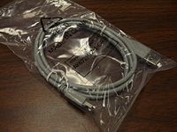
| 1 m USB cable, A male to mini B male | Datasheet | |
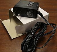
| 9V wall power supply, 0.66A, 2.1mm ID x 5.5mm OD, 6W, center positive. Model EPS090066-P5P from CUI Inc. | Datasheet | |
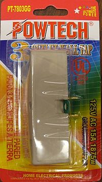
| 1 to 3 power outlet, 2 prong to 3 prong outlet | Powtech PT-7803GG | |
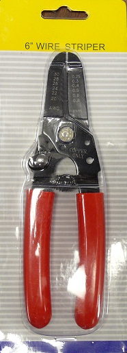
| Wire strippers, for 30, 28, 26, 24, 22, and 20 AWG wire. Can also be used as pliers and to cut wire. Do not try to cut anything else with these, they will get dull | Sparkfun wire strippers | |
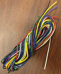
| 6 colors of ~6" sections of 22 AWG solid core wire (red, white, yellow, green, black, blue) | no link | |
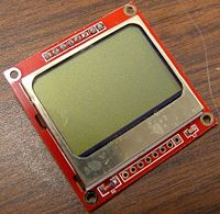
| Monochrome Nokia LCD, 84x48 pixels, using SPI communication | Nokia 5110, Datasheet, [[2]] | |
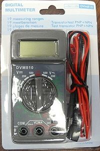
| Small multimeter, Velleman DVM810. Does not have automatic shutoff. Battery will not last more than 12 hours if left on. | Multimeter, Datasheet | |
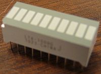
| 10 LED array, green. | Datasheet | |
| 9 pin, 8 resistor, 330 Ohm common cathode bus. Dot indicates common pin. For use with the LED array. | Datasheet | |
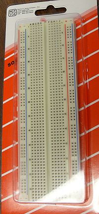
| Extra breadboard, 830 tie points. | 830 T/P Breadboard | |
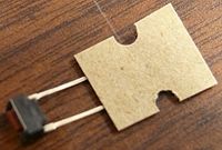
| Momentary NO pushbutton. | Datasheet |
