Difference between revisions of "Persistence-of-Vision Display"
| Line 3: | Line 3: | ||
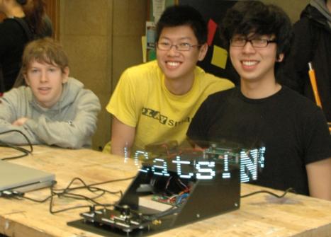
* Gregory McGlynn(Computer Science, Class of 2011) [left] |
* Gregory McGlynn(Computer Science, Class of 2011) [left] |
||
* Kwang Xiong Sim (Mechanical Engineering, Class of 2010) [center] |
* Kwang Xiong Sim (Mechanical Engineering, Class of 2010) [center] |
||
* Alexander Park (Material Science, Class of |
* Alexander Park (Material Science, Class of 2009) [right] |
||
<br clear="all"> |
<br clear="all"> |
||
== Overview == |
== Overview == |
||
Revision as of 00:25, 19 March 2009
Team Members
- Gregory McGlynn(Computer Science, Class of 2011) [left]
- Kwang Xiong Sim (Mechanical Engineering, Class of 2010) [center]
- Alexander Park (Material Science, Class of 2009) [right]
Overview
The purpose of this project was to create a display using the concept of Persistence of Vision. Essentially, we created a rotating platform that spins a column of LEDs. By controlling the frequency of blinking on each LED, and synchronizing it with the rate of rotation of the platform, we can tune the moving column of LEDs to display a desired image.
Theory of Persistence of Vision
Although arguably much more complex, human vision functions in a manner similar to modern motion pictures; our eyes retain images for a fraction of a second, not unlike a frame in a movie. This is called the persistence of vision (POV). When images change fast enough, what we see is a subtle blend of what we see now and a fraction of a second ago.
Implementation
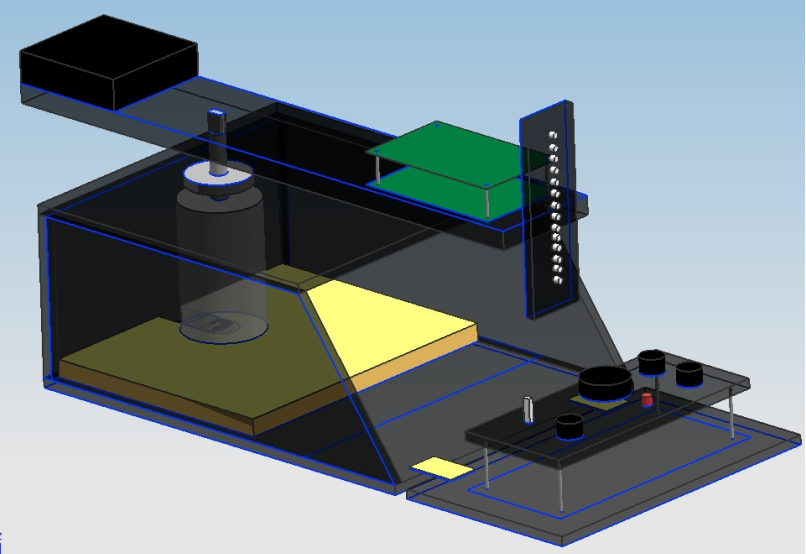
We mounted a platform atop the output shaft of a motor. In order to avoid the complication of wiring a spinning object, all of the major components of the POV display are built on this platform, including a PIC microcontroller, a strip of LEDs, and a battery pack to power the assembly. The strip of LEDs will be mounted vertically at an extended end of the platform. In order to stabilize the spinning motion, the components are positioned so that the center of gravity of the panel passes through the axis of rotation.
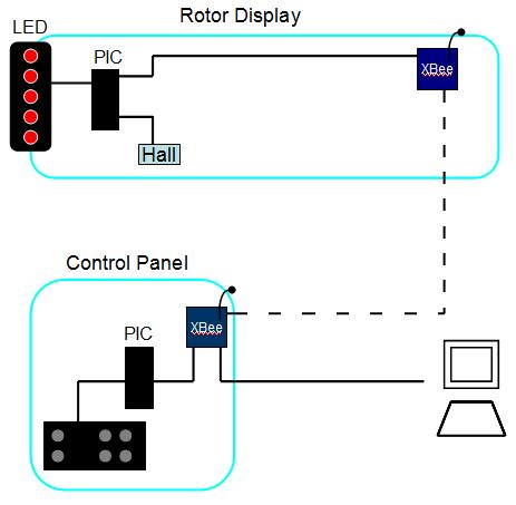
We made use of wireless communication between two PICs to implement live updating of the display based on user input. One PIC will be used to control the POV display and receive wireless information from a second PIC. The second PIC will receive user input store user input and transmit the data wirelessly to the POV’s PIC.
The POV display has two modes of operation. In mode 1, the PIC on the control panel transmits data that we had previously stored in it to the PIC on the rotor panel. By varying the resistance of a potentiometer on the control panel, we allow the user to choose between ten pre-stored messages.
In mode 2 of operation, the PIC on the control panel is connected to a computer via a USB port. Using a Java program that we wrote, we allow the user to draw pictures or type letters which will get updated real time on the POV display.
In order to ensure accurate portrayal of the desired image, we used a hall sensor to implement position sensing. We wired in a hall sensor towards the end of the rotor display panel and attached a magnet on the top of the base box. The magnet was positioned on the orbiting path of the hall sensor so that it registers a signal everytime it spins a round. We have programmed the display to reset the image cycle everytime the hall sensor was triggered so that the image stays at the same location.
Mechanical Design
Base Box
As seen in the above drawing, the base box is built out of rigid expanded PVC. There are 3 rectangle faces, 2 trapezium faces and a door that is hinged at the base so that it opens outwards. The control panel is mounted on the inner face
Control Panel
Rotating Display Panel
Electrical Design
Primary Components
Rotating Display Circuit
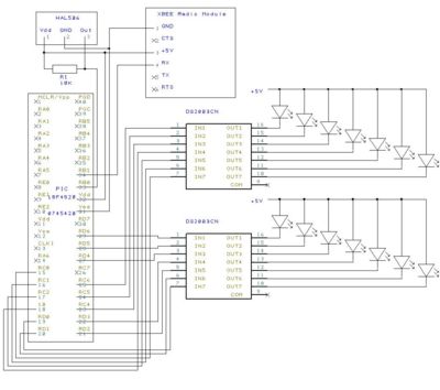
The rotating display has 14 LEDs which are controlled by a PIC. The LEDs are bright and require a good deal of current, which cannot be supplied directly from the output ports of the PIC. Therefore the LEDs are controlled through two Darlington arrays (DS2003). These ICs consist of 7 Darlington pair transistors with a common emitter. The outputs of the PIC are connected to the bases of the transistors. Thus when the PIC drives one of the bases high, current can flow through the transistor and the corresponding LED lights up. We did not find it necessary to use any resistors in this design.
The display uses a Hall Effect Sensor to synchronize its display with its rotation. The circuit as shown causes pin B0 on the PIC to go low whenever the hall sensor is near a magnet. A magnet is mounted at a fixed location under the display so that when the PIC detects this falling edge on pin B0 it knows that it is positioned above the magnet. By timing the interval between two of these events the PIC calculates how fast the display is rotating and adjusts its timing accordingly.
The display receives commands via an XBee radio module.
Control Panel Circuit
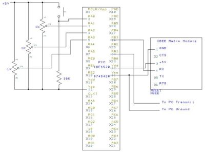
The control panel receives user input through three potentiometers and a pushbutton. The states of these controls are read by the PIC which uses its XBee radio module to send appropriate commands to the display.
If the USB cable is plugged in, the control panel is also responsible for accepting commands from the PC and relaying these commands to the POV through the XBee.
Code
Code for the control panel PIC
Results
Mode 1: Canned Response
In the first mode of operation, a user can just plug in the POV display into a wall socket, turn on the device and display an image immediately. This will allow a quick and easy demonstration without a computer. We have stored ten different responses on the PIC ROM sitting on the rotating display panel. Using a potentiometer, the device allow the user to set which canned response is being displayed.
video link to mode 1
Mode 2: Real time image input
In the second mode of operation, a user can interact more closely with the POV display. In this mode, the POV display is connected via a USB port to a computer which needs to have Java installed. The Java program with the code listed above allows a user to draw pictures or type letters which will be tranmitted real time from the control panel PIC to the rotating display panel PIC through the wireless Xbee chips.
In both modes of operation, we have set up knobs that will allow a user to scroll a message manually or set the scroll speed of an image.
video link to mode 2
Additional Notes
Possible Future Improvements/Enhancements
We have thought about using RGB LEDS to give the display panel more colorful. Also, we can use different sensors to make the display more interactive. For example putting on distance sensors on the display so that the panel color scheme changes when you wave a hand in front of it.
