Difference between revisions of "Three-speaker Chladni Patterns"
Lingyu Xie (talk | contribs) |
Lingyu Xie (talk | contribs) |
||
| Line 220: | Line 220: | ||
=== One-Speaker Chladni === |
=== One-Speaker Chladni === |
||
-add video of one-speaker config |
|||
== Additional Notes == |
== Additional Notes == |
||
Revision as of 22:19, 17 March 2009
Team Members
- Christopher Chow (Mechanical Engineering, Class of 2010)
- Anup Tapase (Electrical Engineering, Class of 2010)
- Lingyu Xie (Electrical Engineering, Class of 2009)
Overview
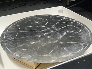
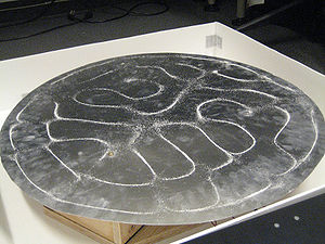
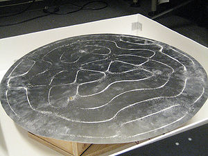
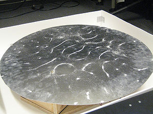
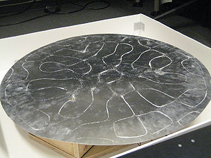
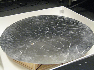
The purpose of this project was to build on the past projects that have been seen on Youtube and other sites involving vibrating a metal plate using one speaker or violin bow. This project uses three speakers separated by 120 degrees which vibrate a circular plate to generate patterns with salt. These patterns are created because when the speakers hit the resonant frequency of the plate, nodes are created on the plate and the salt migrates to these nodes because they are vibrating the least. The project should also include a user interface which the user can use to select different patterns or frequencies for the plate.
Theory
Mechanical Design
Primary Components
Base Box
Three-Speaker Base
Chladni Plate
Electrical Design
Primary Components
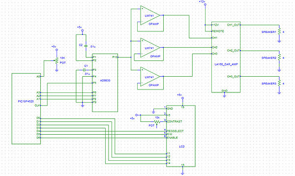
The primary components required to implement the circuit include:
1) PIC 18F4520
2) AD9833 BRMZ-ND Function Generator chip *
3) LM 741 Op Amp (x3)
4) JHD 162A Parallel LCD
5) Car audio amplifier, at least 3-channel (Legacy LA160 4 Channel 300 Watt used here)
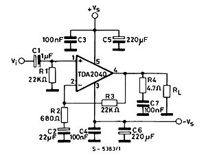
Alternative components that are needed if car amplifier is not available:
1) TDA 2040 audio amplifier chip
*Note: The AD9833 is a surface mount chip, and needs a 10-pin adaptor, 33010CA-ND onto which it is soldered
The PIC communicates with the AD9833 function generator chip through SPI interface. Refer to Waveform Generation with AD9833, and SPI for how to use this chip. The Master Clock is connected to the CLK of the PIC, and the three SPI communication lines are connected to the three I/O pins A1, A2 and A3 on the PIC.
[[ http://hades.mech.northwestern.edu/wiki/images/math/f/b/d/fbd0abe078f3a06ad554be1ffc67e857.png]]
The PIC communicates with the touchscreen through the MAX232N chip. The MAX232N chip regulates the voltage of the input(RXD pin 3) and output(TXD pin 2) of the EXII 7720SC touchscreen chip(between -5V and +5V) to make it between 0 and +5V, since this is the signal range that is accepted by the PIC.
The +5V supply voltages and ground in the circuit can be connected to PIC +5V and ground.
A 10K potentiometer is used to adjust the contrast of the LCD.
The LCD displays X and Y coordinates starting from X:0 Y:0 to about X:16383 Y:16383 (this is when all the bits of X and Y are 1: 0011 1111 1111 1111). This means the touchscreen has 14-bit resolution. The origin is at the bottom left of the touchscreen as oriented in the photo on the right.
Note: When wiring the touchscreen you have a couple of options. The first option is to buy the appropriate connecting cables for the EXII 7720SC chip to interface with a PIC. If this is not a feasible option then a second option would be to take spare rainbow ribbon cable and fashion your own connecting cable. This can be down with a wire stripper and soldering. The circuit pictured here is an example of the second option.
Circuit Notes
Circuit Diagram
Code
Main frequency sweep code
The first thing that this code does is that it initializes the variables target_freq_reg and old_target_freq_reg to the register value of 298 Hz, which is a non-resonant frequency. See Waveform_Generation_with_AD9833,_and_SPI to find out how to convert between frequency and register value for commands sent to the AD9833 function generator chip, and sending commands to the AD9833 using SPI. After this, the analog port pin is set up and the lcd_init() function is called to set up the LCD display. The LCD displays the current frequency that the AD9833 is currently outputting and the target frequency that the chip is supposed to sweep up/down to. See C Example: Parallel Interfacing with LCDs to learn about how to interface and send information to the LCD.
Once the initial set up information is finished, the code sends the first frequency command to the AD9833, starting it at a frequency of 298 Hz by giving it the target_freq_reg register value (initialized at 298 Hz). This allows the speakers to sweep up to the first resonant frequency and oscillate the salt into the first resonant shape when the system is turned on. The register values are then converted to Hz and displayed on the LCD. From there, the code goes into a while() loop which continuously checks the input from the user interface knob which indicates the target frequency that the AD9833 should go to. After getting the target frequency from check_input(), the code compares this new frequency information to the old frequency information (old_freq_reg). If they are different, then the knob was switched to a new frequency and the AD9833 needs to sweep up or down to the new frequency. Depending on whether the new frequency is above or below the old frequency, a for-loop will keep sending new frequency register commands to the AD9833, shifting up or down by 1 Hz every 100 ms, constantly updating the LCD to display the current and target frequency, until the actual frequency is equal to the target frequency. The function check_input() is called for each iteration of the for-loop to check if the target frequency was changed. The old_target_freq_reg is then set equal to the target_freq_reg and the program then holds at this one resonant frequency until the knob sends a different target_freq_reg.
#include <18f4520.h>
#DEVICE ADC=8                   // set ADC to 8 bit accuracy
#use delay(clock=40000000)
#include "flex_lcd.c"             //must include in order to output to LCD
#use spi(DO = PIN_A3, CLK = PIN_A2, ENABLE = PIN_A1, BITS = 16, MASTER, ENABLE_ACTIVE = 0, MSB_FIRST, IDLE = 1)

int16 freq,target_freq;
int16 target_freq_reg, old_target_freq_reg;
int8 knob_val=0;

void check_input();

void main()
{
   int16 ct;

   target_freq_reg=2000+16384;         // initialize starting frequency of speakers to 298 Hz (non-resonant)
   old_target_freq_reg=2000+16384;     // set old target freq variable to equal target freq

   setup_adc_ports(AN0);               // Set up analog input port as pin A0
   setup_adc(ADC_CLOCK_INTERNAL);

   lcd_init();  // Always call this first.

   //INITIAL FREQUENCY FOR AD9833
   spi_xfer(0b0010000100000000); //format command, output sine wave

   spi_xfer(target_freq_reg);    //1st set of bits, 14 LSB, this range is good enough for our use
                                 //send the target frequency register value (freq + 16384) to AD9833 chip
   spi_xfer(0b0100000000000000); //2nd set of bits, 14 MSB

   spi_xfer(0b1100000000000000); //phase register: 0 phase shift (B0-B13)

   spi_xfer(0b0000000000000000); //unformat

   freq=(float).149011 * (float)(target_freq_reg - 16384);  //convert the target freq register value to actual freq value
   target_freq=freq; // initialize target freq as current freq

   printf(lcd_putc,"\fFreq: %Lu Hz\n",freq); //display current freq
   printf(lcd_putc,"Target: %Lu H\n",target_freq); //display target freq

   while(TRUE)
   {
      check_input(); //check the knob input to see if target frequency has changed

      if(old_target_freq_reg != target_freq_reg) //go in here if target freq changed after calling check_input()
      {
         if(target_freq_reg > old_target_freq_reg) //sweep up to target freq
         {
            for(ct=old_target_freq_reg; ct<=target_freq_reg; ct=ct+7) //ct+7 approximate increases frequency by 1 Hz
            {
               spi_xfer(0b0010000100000000);

               spi_xfer(ct); //set AD9833 frequency to ct, which is freq register that is sweeping up by 7 each time loop is run
               spi_xfer(0b0100000000000000);

               spi_xfer(0b1100000000000000);

               spi_xfer(0b0000000000000000);

               freq=(float).149011 * (float)(ct - 16384);
               target_freq=(float).149011 * (float)(target_freq_reg - 16384);

               printf(lcd_putc,"\fFreq: %Lu Hz\n",freq); //display current freq
               printf(lcd_putc,"Target: %Lu Hz\n",target_freq); //display target freq

               check_input(); //see if knob position has selected different target freq
               delay_ms(90);  //delay to allow speakers to play freq for 90 ms + 10 ms (in check_input() function)
            }

            old_target_freq_reg = target_freq_reg; //reached target freq, set both variables equal until knob position changed

         }
         else if(target_freq_reg < old_target_freq_reg) //sweep down to target freq
         {
            for(ct=old_target_freq_reg; ct>=target_freq_reg; ct=ct-7) //ct+7 approximate decreases frequency by 1 Hz
            {
               spi_xfer(0b0010000100000000);

               spi_xfer(ct); //set AD9833 frequency to ct, which is freq register that is sweeping down by 7 each time loop is run
               spi_xfer(0b0100000000000000);

               spi_xfer(0b1100000000000000);

               spi_xfer(0b0000000000000000);


               freq=(float).149011 * (float)(ct - 16384); //convert current freq register value (ct) to frequency value
               target_freq=(float).149011 * (float)(target_freq_reg - 16384); //convert target freq register to target freq value

               printf(lcd_putc,"\fFreq: %Lu Hz\n",freq); //display current freq
               printf(lcd_putc,"Target: %Lu Hz\n",target_freq); //display target freq

               check_input(); //see if knob position has selected different target freq
               delay_ms(90);  //delay to allow speakers to play freq for 90 ms + 10 ms (in check_input() function)
            }

            old_target_freq_reg = target_freq_reg; //reached target freq, set both variables equal until knob position changed
         }
      }
   }
}
Checking user input
This function is used to check the knob/potentiometer position at certain points during the changing of frequencies in the main function. It sets the ADC channel to 0 and takes the analog input from pin A0 on the PIC using read_adc(). This input, set to the variable knob_val, is an integer between 0-255 which corresponds to the voltage coming out of the knob/potentiometer, which is 0 if the output is at 0V and 255 if the output is at 5V. By checking if knob_val is between a certain integer range corresponding to the different numbers on the knob (numbered 0-10), the target frequency can be set by the user. Nine target resonant frequencies were programmed in this function based on the good clarity of the shapes they produced on the plate, but more resonant frequencies exist and can be added to the if-statement in this function. The target frequency registers should be adjusted depending on the plate shape and size.
void check_input() //check knob position to see if target freq has changed
{
      set_adc_channel(0);     // Set the analog input channel to 0
      delay_us(10);           // wait 10uS for ADC to settle to a newly selected input
      knob_val = read_adc();  // Read in knob user input to tell speakers what resonant freq to sweep up to

      delay_ms(10);           // delay 10 ms to allow reading of analog input

      //check and set target_freq_reg according to knob position (0-255 values split into 9 discrete levels)
      if (knob_val >= 0 && knob_val< 22 )
         target_freq_reg = 2281+16384; //339 Hz
      else if(knob_val >= 22 && knob_val< 54)
         target_freq_reg = 3308+16384; //493 Hz
      else if(knob_val >= 54 && knob_val< 86)
         target_freq_reg = 3778+16384; //563 Hz
      else if(knob_val >= 86 && knob_val< 117)
         target_freq_reg = 3986+16384; //594 Hz
      else if(knob_val >= 117 && knob_val< 147)
         target_freq_reg = 4207+16384; //627 Hz
      else if(knob_val >= 147 && knob_val< 178)
         target_freq_reg = 4362+16384; //650 Hz
      else if(knob_val >= 178 && knob_val< 209)
         target_freq_reg = 5006+16384; //746 Hz
      else if(knob_val >= 209 && knob_val< 239)
         target_freq_reg = 5308+16384; //791 Hz
      else if(knob_val >= 239 && knob_val< 255)
         target_freq_reg = 5872+16384; //875 Hz
}
Results
Three-Speaker Chladni
One-Speaker Chladni
-add video of one-speaker config
Additional Notes
Possible Future Improvements/Enhancements
-Try sending different frequencies (by figuring out how to program multiple AD9833 chips) to each speaker to see if they generate different patterns
-Use different plate size or add 4th speaker and use large square plate to change the types of visible shapes at resonance
-Figure out issue with TDA-2040 audio amp so the project wouldn't have to rely on car audio amp
-Use more rigid plate or construct one with less defects in shape
