Difference between revisions of "Stepper motor control with the PIC"
TylerMiller (talk | contribs) (→Code) |
|||
| (19 intermediate revisions by 2 users not shown) | |||
| Line 1: | Line 1: | ||
== Original Assignment == |
|||
| ⚫ | |||
The project is to use an interrupt to achieve stepper motor control along arbitrary motion profiles (e.g., mathematical functions of time, including constant velocity profiles). For example, if your interrupt is at 1 ms, you can compare your desired step count at the current time to the desired step count at the current time and step the motor forward, backward, or not at all, as appropriate. A simpler variant of this is constant speed control: the main program sets the speed, and the interrupt determines whether or not to step the motor at each interrupt time. Your documentation must provide evidence that the interrupt service routine always completes in less time than the time between interrupts (e.g., you can use the oscilloscope and look at a pin going high at the beginning of the ISR and low at the end). |
|||
Stepper motors are particularly useful devices because they can generate precise movement open loop. There is lots of information about stepper motors on the web and the wiki. Refer to the further reading section below as a place to get started. |
|||
Also, stepper motors tend to have relatively low torque, but are capable of high speeds. To improve the torque, we can add a gearhead or other transmission element. It is convenient to have the motor and gearhead in a single package, so if you see a relatively inexpensive stepper motor + gearhead combination in an appropriate size, let us know! |
|||
This page provides explanation of the circuitry and example code for driving the [[Actuators Available in the Mechatronics Lab#Stepper_Motors|Jameco 163395 8.4V bipolar stepper motor]] available in the mechatronics lab. The rated motor voltage is 8.4 volts but the motor should be able to handle up to 12V. When operating at higher voltages be mindful of the possibility of overheating. In this example, we used 8.6V. The motor is connected to a L293B H-bridge chip controlled by the logic outputs from the PIC. The PIC reads the voltage from a potentiometer connected to an analog input and converts it to a desired speed and number of interrupt service routine (ISR) calls until stepping. The ISR drives the logic outputs controlling the H-bridge and motor. |
|||
| ⚫ | |||
This stepper motor contains two windings, each of which has a set of two wires that allow for polarity control. One winding is operated by the blue and red wires, while the other is controlled by the yellow and white wires. |
|||
The ISR completes in about 2.5 us. Which means that the motor can be commanded to step extremely quickly. However, the rotor can only keep up with the signal for a limited range, and can move one full step every ~1.2 ms. With a mass attached to the output shaft the maximum speed will decrease. |
|||
== Circuit == |
== Circuit == |
||
| Line 42: | Line 45: | ||
== Code == |
== Code == |
||
* [[media: |
* [[media:main.c|stepper_control.c]] - Code can be found here. |
||
==Further Reading== |
|||
===Wiki Pages=== |
|||
* [[Stepper Motor Theory]] |
|||
* [[Stepper Motor Circuits]] |
|||
* [[Unipolar Stepper Motor Driver Circuit]] |
|||
===Microchip Application Notes=== |
|||
* [[media:00907a.pdf|Stepping Motors Fundamentals]] [http://www.microchip.com/stellent/idcplg?IdcService=SS_GET_PAGE&nodeId=1824&appnote=en012151 -Microchip Document Description] |
|||
* [[media:00822a.pdf|Stepper Motor Microstepping with PIC18C452]] [http://www.microchip.com/stellent/idcplg?IdcService=SS_GET_PAGE&nodeId=1824&appnote=en011997 -Microchip Document Description] |
|||
Latest revision as of 16:41, 2 March 2008
Overview
Stepper motors are particularly useful devices because they can generate precise movement open loop. There is lots of information about stepper motors on the web and the wiki. Refer to the further reading section below as a place to get started.
This page provides explanation of the circuitry and example code for driving the Jameco 163395 8.4V bipolar stepper motor available in the mechatronics lab. The rated motor voltage is 8.4 volts but the motor should be able to handle up to 12V. When operating at higher voltages be mindful of the possibility of overheating. In this example, we used 8.6V. The motor is connected to a L293B H-bridge chip controlled by the logic outputs from the PIC. The PIC reads the voltage from a potentiometer connected to an analog input and converts it to a desired speed and number of interrupt service routine (ISR) calls until stepping. The ISR drives the logic outputs controlling the H-bridge and motor.
This stepper motor contains two windings, each of which has a set of two wires that allow for polarity control. One winding is operated by the blue and red wires, while the other is controlled by the yellow and white wires.
The ISR completes in about 2.5 us. Which means that the motor can be commanded to step extremely quickly. However, the rotor can only keep up with the signal for a limited range, and can move one full step every ~1.2 ms. With a mass attached to the output shaft the maximum speed will decrease.
Circuit
Wiring Up The L293B
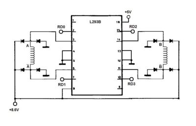
A DIP16-L293B quad push pull driver is used to control the two windings for the bipolar stepper motor. The provided battery pack for your Mechatronics Lab Kit with the 5V regulator connects into pin 16, the logic supply voltage. A +8.6V voltage from the available power supply handled the necessary voltage to power the motor itself, and feeds into pin 8.
The PIC's output channels RD0-RD3 wire directly into the L293B's four inputs. The blue and red wires pertaining to one set of windings connect to pins 3 and 5 of the L293B, and the white and yellow wires for the other half go to pins 11 and 14. The remaining pins 4,5,12 and 13 all connect to a common ground.
A spec sheet for the L293B can be found here. [1]
Adjusting The Speed With A Trimpot
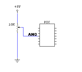
A convenient method of providing a varying input for the stepper motor is with a trimpot, or potentiometer. This circuit utilized a 10k Ohm trimpot to control the speed of the stepper motor along with the direction. The middle wiper connected to pin AN0 of the PIC for analog readouts to help determine what desired speeds and direction are needed. Zero voltage and the max +5V will emulate maximum speed for forwards and backwards directions, with the capability of slower intermediate speeds. The +2.5V threshold will switch the direction for the motor.
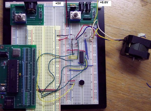
Completed Circuit
The resultant circuit should look like the image below.
Code
- stepper_control.c - Code can be found here.


