Difference between revisions of "NU32: Driving a stepper motor"
NickMarchuk (talk | contribs) |
|||
| (10 intermediate revisions by one other user not shown) | |||
| Line 1: | Line 1: | ||
'''THIS PAGE REFERS TO A PRE-RELEASE VERSION OF THE NU32 PIC32 DEVELOPMENT BOARD. FOR INFORMATION, SAMPLE CODE, AND VIDEOS RELATED TO THE PRODUCTION VERSION (2016 AND LATER), AND TO THE CORRESPONDING BOOK "EMBEDDED COMPUTING AND MECHATRONICS WITH THE PIC32 MICROCONTROLLER," VISIT [[NU32|THE NU32 PAGE]].''' |
|||
Driving a unipolar stepper motor using the TB6612 H-bridge and the NU32 |
Driving a unipolar stepper motor using the TB6612 H-bridge and the NU32 |
||
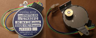
[[Image:NU32_stepperMotor.jpg|thumb|400px| |
[[Image:NU32_stepperMotor.jpg|thumb|400px|A unipolar stepper motor|center]] |
||
== Overview == |
== Overview == |
||
More information about stepper motors can be found [[Stepper Motor Theory| here]], [[Stepper Motor Circuits| here]], and [http://en.wikipedia.org/wiki/Stepper_motor here]. |
|||
[[Media:TB6612.pdf|Datasheet]] |
|||
The stepper motor included in the NU32 motor kit is a unipolar stepping motor with 95 ohms per half coil and a 7.5 degree per step size. It has a 3:25 gearhead, so the output shaft will make 1 revolution after 400 steps. |
|||
The TB6612 is a MOSFET based motor driver. |
|||
We will ignore the center taps of the unipolar motor and treat it as a bipolar motor, so that we can drive it with both bridges on the TB6612. |
|||
[[Media:TB6612.pdf|H-Bridge datasheet for driving the stepper motor]] |
|||
To make the motor step, we need to turn on the coils in a specific order. We need to have positive current or negative current going through the coils like this: |
|||
<table border=1> |
|||
<tr> |
|||
<td>Coil 1</td><td>Coil 2</td> |
|||
</tr> |
|||
<tr> |
|||
<td>+</td><td>+</td> |
|||
</tr> |
|||
<tr> |
|||
<td>+</td><td>-</td> |
|||
</tr> |
|||
<tr> |
|||
<td>-</td><td>-</td> |
|||
</tr> |
|||
<tr> |
|||
<td>-</td><td>+</td> |
|||
</tr> |
|||
</table> |
|||
The direction of the coil current is controlled by the TB6612. We always want the current on, so fix the PWM pin high. For positive current, we want OUT1 to be high, and OUT2 to be low. This corresponds to IN1 to be high, and IN2 to be low. To get negative current, we reverse the input pins. |
|||
In code, we will run through the table above at a fixed frequency to get a constant stepping speed. We will create a global variable, stepIndex, to know which coil state we are in, and use a switch() statement to know which state to go to next. By increasing stepIndex will will move in one direction, and decreasing stepIndex will rotate in the other direction. We must be careful to rollover stepIndex so that there are only 4 states. |
|||
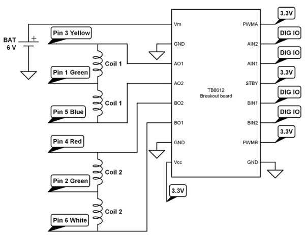
== Wiring == |
|||
[[Image:NU32_stepper_wireup.png|thumb|600px|center]] |
|||
== Code == |
|||
The following code, [[Media:NU32_stepper_example.c | NU32_stepper_example.c]], uses timer 2 to step through the stepping sequence at 25Hz, resulting in 1 revolution of the output shaft ever 16s. Press and hold the USER button to reverse direction. |
|||
Try increasing the frequency of timer 2. At above 100Hz stepping (1 rev per 4s), my motor starts missing steps, and at 100Hz has almost no torque. Increasing the battery voltage would allow you to increase the motor speed and torque. |
|||
== Details == |
== Details == |
||
| Line 13: | Line 51: | ||
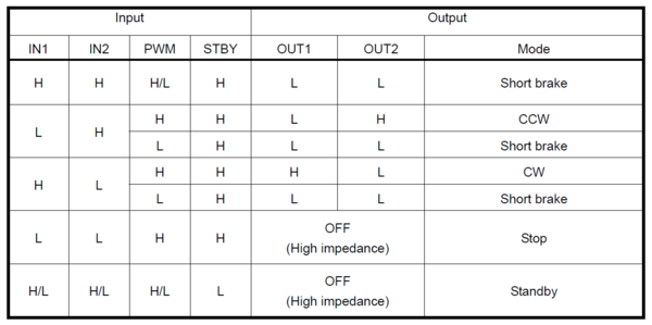
[[Image:TB6612.png|thumb|600px|The TB6612 logic table|center]] |
[[Image:TB6612.png|thumb|600px|The TB6612 logic table|center]] |
||
Latest revision as of 05:39, 16 January 2016
THIS PAGE REFERS TO A PRE-RELEASE VERSION OF THE NU32 PIC32 DEVELOPMENT BOARD. FOR INFORMATION, SAMPLE CODE, AND VIDEOS RELATED TO THE PRODUCTION VERSION (2016 AND LATER), AND TO THE CORRESPONDING BOOK "EMBEDDED COMPUTING AND MECHATRONICS WITH THE PIC32 MICROCONTROLLER," VISIT THE NU32 PAGE.
Driving a unipolar stepper motor using the TB6612 H-bridge and the NU32
Overview
More information about stepper motors can be found here, here, and here.
The stepper motor included in the NU32 motor kit is a unipolar stepping motor with 95 ohms per half coil and a 7.5 degree per step size. It has a 3:25 gearhead, so the output shaft will make 1 revolution after 400 steps.
We will ignore the center taps of the unipolar motor and treat it as a bipolar motor, so that we can drive it with both bridges on the TB6612.
H-Bridge datasheet for driving the stepper motor
To make the motor step, we need to turn on the coils in a specific order. We need to have positive current or negative current going through the coils like this:
| Coil 1 | Coil 2 |
| + | + |
| + | - |
| - | - |
| - | + |
The direction of the coil current is controlled by the TB6612. We always want the current on, so fix the PWM pin high. For positive current, we want OUT1 to be high, and OUT2 to be low. This corresponds to IN1 to be high, and IN2 to be low. To get negative current, we reverse the input pins.
In code, we will run through the table above at a fixed frequency to get a constant stepping speed. We will create a global variable, stepIndex, to know which coil state we are in, and use a switch() statement to know which state to go to next. By increasing stepIndex will will move in one direction, and decreasing stepIndex will rotate in the other direction. We must be careful to rollover stepIndex so that there are only 4 states.
Wiring
Code
The following code, NU32_stepper_example.c, uses timer 2 to step through the stepping sequence at 25Hz, resulting in 1 revolution of the output shaft ever 16s. Press and hold the USER button to reverse direction.
Try increasing the frequency of timer 2. At above 100Hz stepping (1 rev per 4s), my motor starts missing steps, and at 100Hz has almost no torque. Increasing the battery voltage would allow you to increase the motor speed and torque.
Details
Use the following table to determine the motor output:
More Information
NA


