Difference between revisions of "Resistors (Ohm's Law), Capacitors, and Inductors"
| (37 intermediate revisions by 5 users not shown) | |||
| Line 1: | Line 1: | ||
__TOC__ |
__TOC__ |
||
==Resistors== |
==Resistors== |
||
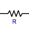
The symbol for a resistor: |
The symbol for a resistor: [[Image:Resistor_symbol.gif]] |
||
[[Image: |
Real resistors:[[Image:real_resistor_photo.jpg|100 px]] |
||
Try [http://en.wikipedia.org/wiki/Resistors wikipedia] for more on resistors and for the [http://en.wikipedia.org/wiki/Electronic_color_code#Resistors.2C_capacitors_and_inductors resistor color codes]. |
|||
The relationship between the current through a conductor with resistance and the voltage across the same conductor is described by '''Ohm's law''': |
The relationship between the current through a conductor with resistance and the voltage across the same conductor is described by '''Ohm's law''': |
||
| Line 15: | Line 17: | ||
<math>P=IV\,</math> |
<math>P=IV\,</math> |
||
If |
If ''I'' is measured in amps and ''V'' in volts, then the power ''P'' is |
||
in watts. |
in watts. |
||
By plugging in different forms of |
By plugging in different forms of ''V=IR'', we can rewrite ''P=IV'' as: |
||
<math>P=I^2R\,</math> |
<math>P=I^2R\,</math> |
||
| Line 29: | Line 31: | ||
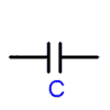
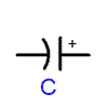
The symbol for a capacitor: |
The symbol for a capacitor: |
||
[[Image:Capacitor_symbol. |
[[Image:Capacitor_symbol.gif]] or [[Image:Capacitor_polarized_symbol.gif]] |
||
The capacitor on the right is ''polarized''. The potential on the straight side (with the plus sign) should always be higher than the potential on the curved side. |
|||
A capacitor is a device that stores electric charges. (Do not confuse this with a battery; a battery creates an electric potential difference, but doesn't store charge. A battery is analogous to a water pump, while a capacitor is analogous to a water tank.) At steady state, a capacitor has a constant voltage across it and zero current through it. |
|||
Real capacitors:[[Image:capacior_photo.jpg|100 px]] |
|||
Notice that the capacitor on the far right is polarized; the negative terminal is marked on the can with white negative signs. The polarization is also indicated by the length of the leads: the short lead is negative, the long lead is positive. |
|||
A capacitor is a device that stores electric charges. '''The current through a capacitor can be changed instantly, but it takes time to change the voltage across a capacitor.''' |
|||
The unit of measurement for the capacitance of a capacitor is the ''farad'', which is equal to 1 coulomb per volt. |
The unit of measurement for the capacitance of a capacitor is the ''farad'', which is equal to 1 coulomb per volt. |
||
| Line 53: | Line 62: | ||
<math>v(t')=\frac{1}{C} \int_{-\infty}^{t'} i(t)dt</math> |
<math>v(t')=\frac{1}{C} \int_{-\infty}^{t'} i(t)dt</math> |
||
The energy stored in a capacitor (in joules) is given by the equation: |
|||
or |
|||
<math> |
<math>w_C(t)=\frac{1}{2}Cv^2</math> |
||
==Inductors== |
|||
which is equivalent to the first equation. |
|||
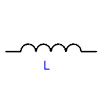
The symbol for an inductor: |
|||
[[Image:inductor_symbol.gif]] |
|||
Assuming the same zero initial states as before, the energy stored in a capacitor (in joules) is given by the equation: |
|||
Real inductors (and items with inductance):[[Image:inductors_photo.jpg|100 px]] |
|||
<math>u(t)=\frac{1}{2}Cv^2</math> |
|||
An inductor stores energy in the form of a magnetic field, usually by means of a coil of wire. An inductor resists change in the current flowing through it. '''The voltage across an inductor can be changed instantly, but an inductor will resist a change in current.''' |
|||
==Inductors== |
|||
The symbol for an inductor: |
|||
Unless we are tuning an oscillator or something, we generally don't purposefully add inductors to mechatronics circuits. However, any device with coils, such as motors or transformers, add inductance to a circuit. |
|||
The relationship between the voltage across the inductor is linearly related by a factor ''L'', the inductance, to the time rate of change of the current through the inductor. The unit for inductance is the ''henry'', and is equal to a volt-second per ampere. |
|||
The relationship between the voltage and the current is as follows: |
|||
<math>v(t)=L \frac {di}{dt}</math> |
|||
If we multiply both sides by ''dt'', we get: |
|||
<math>di=\frac{1}{L}vdt</math> |
|||
Integrating both sides from <math>t_0</math> to <math>t'</math> gives: |
|||
<math>i(t')-i(t_0)=\frac{1}{L}\int_{t_0}^{t'}vdt</math> |
|||
which is equal to: |
|||
<math>i(t')=\frac{1}{L}\int_{t_0}^{t'}vdt+i(t_0)</math> |
|||
assuming that the voltage, current and energy of the inductor are all zero at <math>t=-\infty</math> reduces the equation to |
|||
<math>i(t')=\frac{1}{L}\int_{-\infty}^{t'}vdt</math> |
|||
The energy stored in the inductor is given by: |
|||
<math>w_L(t)=\frac{1}{2}Li^2</math> |
|||
==Elements in Series and Parallel== |
|||
Resistors connected in '''series''' and '''parallel''': |
|||
[[Image:series_parallel_resistors.gif]] |
|||
{| border="1" cellspacing="0" cellpadding="5" align="center" |
|||
|+Two Elements in Series and Parallel |
|||
! !!Resistor !! Capacitor !! Inductor |
|||
|- |
|||
|Series || <math>R_{eq}=R_1+R_2\,</math> || <math>C_{eq}=\frac{C_1 C_2}{C_1+C_2}</math> || <math>L_{eq}=L_1+L_2\,</math> |
|||
|- |
|||
|Parallel || <math>R_{eq}=\frac{R_1 R_2}{R_1+R_2}</math> ||<math>C_{eq}=C_1+C_2\,</math> || |
|||
<math>L_{eq}=\frac{L_1 L_2}{L_1+L_2}</math> |
|||
|} |
|||
===More than 2 Elements in series or parallel=== |
|||
Here we provide the equations for calculating the equivalant resistance of three or more resistors in parallel; the same form can be applied to the corresponding equations for capacitors and inductors. Of course, you can always just simplify a network of elements by combining two at a time using the equations above. |
|||
To find the combined resistance of resistors connected in series, simply add the resistances: |
|||
<math>R_{eq}=R_1+R_2+\cdot\cdot\cdot+R_n</math> |
|||
If the resistors are connected in parallel, the equation is: |
|||
<math>\frac{1}{R_{eq}}=\frac{1}{R_1}+\frac{1}{R_2}+\cdot\cdot\cdot+\frac{1}{R_n}</math> |
|||
====Proof for Resistors in Parallel equation==== |
|||
Here we provide the derivation for the parallel resistors equation. The corresponding equations for capacitors and inductors can be derived with a similar method. |
|||
[[Image:Parallel_resistors.gif]] |
|||
We can prove the equation for parallel resistors by using Kirchhoff's voltage and current laws: |
|||
<math>V_s=V_{R1}=V_{R2}\,</math> (KVL) |
|||
<math>I_s=I_1+I_2\,</math> (KCL) |
|||
Plugging in the constitutive law for resistors in the second equation yields: |
|||
<math>I_s=\frac{V_s}{R_1}+\frac{V_s}{R_2}=V_s\left(\frac{1}{R_1}+\frac{1}{R_2}\right)=V_s\left(\frac{R_1+R_2}{R_1R_2}\right) |
|||
</math> |
|||
<math> |
|||
[[Image:inductor_symbol.jpg]] |
|||
R_{eq}=\frac{V_s}{I_s}=\frac{R_1R_2}{R_1+R_2} |
|||
</math> |
|||
==References== |
|||
An inductor stores energy in the form of a magnetic field. |
|||
Hayt, William H. Jr., Jack E. Kemmerly, and Steven M. Durbin. <u>Engineering Circuit Analysis</u>. 6th ed. New York:McGraw-Hill, 2002. |
|||
Latest revision as of 08:27, 25 July 2006
Resistors
Try wikipedia for more on resistors and for the resistor color codes.
The relationship between the current through a conductor with resistance and the voltage across the same conductor is described by Ohm's law:
where V is the voltage across the conductor, I is the current through the conductor, and R is the resistance of the conductor.
The power dissipated by the resistor is equal to the voltage multiplied by the current:
If I is measured in amps and V in volts, then the power P is in watts.
By plugging in different forms of V=IR, we can rewrite P=IV as:
or
Capacitors
The symbol for a capacitor:
The capacitor on the right is polarized. The potential on the straight side (with the plus sign) should always be higher than the potential on the curved side.
Notice that the capacitor on the far right is polarized; the negative terminal is marked on the can with white negative signs. The polarization is also indicated by the length of the leads: the short lead is negative, the long lead is positive.
A capacitor is a device that stores electric charges. The current through a capacitor can be changed instantly, but it takes time to change the voltage across a capacitor.
The unit of measurement for the capacitance of a capacitor is the farad, which is equal to 1 coulomb per volt.
The charge(q), voltage (v), and capacitance(C) of a capacitor are related as follows:
where q(t) and v(t) are the values for charge and voltage, expressed as a function of time.
Differentiating both sides with respect to time gives:
Rearranging and then integrating with respect to time give:
If we assume that the charge, voltage, and current of the capacitor are zero at , our equation reduces to:
The energy stored in a capacitor (in joules) is given by the equation:
Inductors
The symbol for an inductor:
Real inductors (and items with inductance):
An inductor stores energy in the form of a magnetic field, usually by means of a coil of wire. An inductor resists change in the current flowing through it. The voltage across an inductor can be changed instantly, but an inductor will resist a change in current.
Unless we are tuning an oscillator or something, we generally don't purposefully add inductors to mechatronics circuits. However, any device with coils, such as motors or transformers, add inductance to a circuit.
The relationship between the voltage across the inductor is linearly related by a factor L, the inductance, to the time rate of change of the current through the inductor. The unit for inductance is the henry, and is equal to a volt-second per ampere.
The relationship between the voltage and the current is as follows:
If we multiply both sides by dt, we get:
Integrating both sides from to gives:
which is equal to:
assuming that the voltage, current and energy of the inductor are all zero at reduces the equation to
The energy stored in the inductor is given by:
Elements in Series and Parallel
Resistors connected in series and parallel:
| Resistor | Capacitor | Inductor | |
|---|---|---|---|
| Series | |||
| Parallel |
|
More than 2 Elements in series or parallel
Here we provide the equations for calculating the equivalant resistance of three or more resistors in parallel; the same form can be applied to the corresponding equations for capacitors and inductors. Of course, you can always just simplify a network of elements by combining two at a time using the equations above.
To find the combined resistance of resistors connected in series, simply add the resistances:
If the resistors are connected in parallel, the equation is:
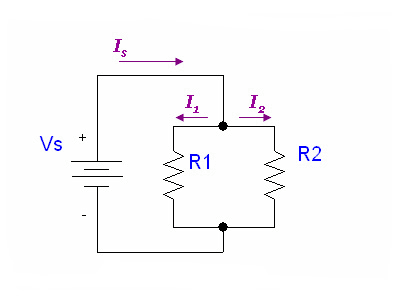
Proof for Resistors in Parallel equation
Here we provide the derivation for the parallel resistors equation. The corresponding equations for capacitors and inductors can be derived with a similar method.
We can prove the equation for parallel resistors by using Kirchhoff's voltage and current laws:
(KVL)
(KCL)
Plugging in the constitutive law for resistors in the second equation yields:
References
Hayt, William H. Jr., Jack E. Kemmerly, and Steven M. Durbin. Engineering Circuit Analysis. 6th ed. New York:McGraw-Hill, 2002.
