Difference between revisions of "555 Servo Circuit"
| (8 intermediate revisions by one other user not shown) | |||
| Line 1: | Line 1: | ||
| ⚫ | |||
==Introduction== |
|||
See also:[[555_Timer]] |
|||
| ⚫ | |||
| ⚫ | |||
==Circuit Construction== |
|||
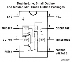
Two 555 timers are used to create the servo control signal. The pinout for the LM555 is shown below: |
Two 555 timers are used to create the servo control signal. The pinout for the LM555 is shown below: |
||
[[image:555_pinout.jpg|center |
[[image:555_pinout.jpg|center|250px]] |
||
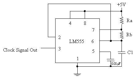
The first 555 timer creates a clock signal at our desired frequency. The circuit for this is shown below: |
The first 555 timer creates a clock signal at our desired frequency. The circuit for this is shown below: |
||
| Line 48: | Line 47: | ||
|} |
|} |
||
Here is a picture of a circuit built using parts in the lab. I replaced Rc with a 10kOhm resistor and a 10k POT to allow some fine tuning. |
|||
[[image:555 servo photo.jpg|center]] |
|||
| ⚫ | |||
<nowiki>Insert non-formatted text here</nowiki> |
|||
Latest revision as of 01:32, 20 March 2009
See also:555_Timer
This page describes how to build a circuit for driving an RC Servo motor. It uses two LM555 IC’s to create the pulse train that drives the motor. For an RC Servo, the width of the “high” pulse determines the angle of the rotor. Sample values for creating a working circuit are given.
Two 555 timers are used to create the servo control signal. The pinout for the LM555 is shown below:
The first 555 timer creates a clock signal at our desired frequency. The circuit for this is shown below:
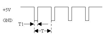
This circuit is referred to as an “Astable Multivibrator” in the LM555 datasheet. The sizes of Ra, Rb, and C1 determine the shape of the clock signal. We want the clock signal to look something like this:
The values of T1 and T are given by
T1=0.693*Rb*C T=0.693*(Ra+2*Rb)*C
We want T to be around 20ms and T1 to be smaller than the minimum pulse width we will send to the RC Servo (T1≤0.3ms). Here’s some sample values:
Ra=330kΩ, Rb=1.5 kΩ, C1=0.1 μF → T1 = 0.1 ms, T=23 ms
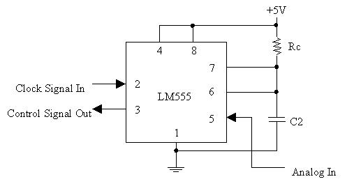
The second 555 Timer circuit is a “pulse width modulator”, shown below:
The combination of Rc and C2 determines the time that the output is high. Good values are
Rc = 15 kΩ C2 = 0.1 μF
which give a time constant of τ = 1.5 ms.
Using the values given in this document, you will get the following relationship:
| Analog In (V) | Control Voltage (V) | Pulse Width (ms) | Servo Position |
|---|---|---|---|
| 1.1 | ~1.1 | ~0.388 | One end |
| 4.4 | ~4.0 | ~2.375 | Other end |
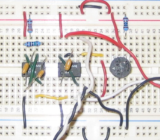
Here is a picture of a circuit built using parts in the lab. I replaced Rc with a 10kOhm resistor and a 10k POT to allow some fine tuning.
Insert non-formatted text here
