Difference between revisions of "Baseball"
JeremyKlem (talk | contribs) |
(→Bat) |
||
| Line 24: | Line 24: | ||
===Bat=== |
===Bat=== |
||
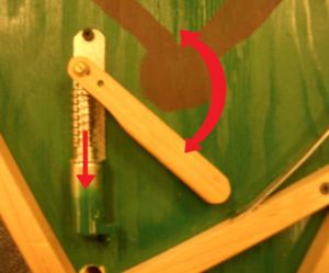
The Bat was fashioned out of wood on the band saw and sanded to a finish. Two holes were drilled: one to act as an anchoring pivot point and the other to be attached to an actuator. A [http://www.goldmine-elec-products.com/prodinfo.asp?number=G16036 Spring Return Solenoid], run on two 9.6V rechargeable batteries, was used to actuate the bat. The user interface was a simple push button usually stocked in the lab. This button was located on the right side of the game similar to where pinball buttons are located. |
The Bat was fashioned out of wood on the band saw and sanded to a finish. Two holes were drilled: one to act as an anchoring pivot point and the other to be attached to an actuator. A [http://www.goldmine-elec-products.com/prodinfo.asp?number=G16036 Spring Return Solenoid], run on two 9.6V rechargeable batteries in series, was used to actuate the bat. The user interface was a simple push button usually stocked in the lab. This button was located on the right side of the game similar to where pinball buttons are located. |
||
In order to make the game more like baseball we set up a system to only allow the user to swing during a pitched ball. To learn more about this look below to '''Bat Relay'''. |
In order to make the game more like baseball we set up a system to only allow the user to swing during a pitched ball. To learn more about this look below to '''Bat Relay'''. |
||
Revision as of 14:09, 23 March 2008
Team Members
Ming Lee Chow: Biomedical Engineering Class of 2008
Jeremy Klem: Mechanical Engineering Class of 2008
Overview
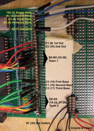
The goal of this project was to make an interactive baseball game inspired by pinball. There is a solenoid-powered bat and a pitching mechanism that utilizes a motor and lever arm setup. Both of these are controlled by buttons so that two people can play against each other. The game has targets for a single, double, triple, and home run, with a simple photodiode-phototransistor circuit to sense the ball. There are LEDs to light up each base as well as a scoreboard containing two seven-segment displays and LEDs for outs.
This page will describe the mechanical design, electrical design, and code for the project.
Mechanical Design
Play Field and Housing
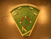
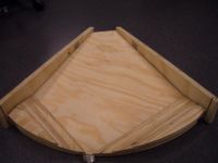
The general concept is to have a slanted surface similar to a pinball machine. The ball will roll down and the user will try to hit it back up into a single, double, triple or homerun. These "hits" have dampening backstops and milled down grooves to channel the ball into a hole where a sensor is placed. If none of these are hit then the ball rolls back down towards the bat and into an out hole. This was done to limit the number of holes and sensor we would need to create. There are rails along the play field so the ball will not fly off. Underneath, there is a recess, which is an oppositely slanted board to channel the ball back to the pitching apparatus. The housing has sides to mount the bat button and keep the ball from sliding out of the recess. A acrylic sheet was used to wrap around the back as the rear wall. Holes were cut to allow pitching and scoreboard display.
Bat
The Bat was fashioned out of wood on the band saw and sanded to a finish. Two holes were drilled: one to act as an anchoring pivot point and the other to be attached to an actuator. A Spring Return Solenoid, run on two 9.6V rechargeable batteries in series, was used to actuate the bat. The user interface was a simple push button usually stocked in the lab. This button was located on the right side of the game similar to where pinball buttons are located.
In order to make the game more like baseball we set up a system to only allow the user to swing during a pitched ball. To learn more about this look below to Bat Relay.
Pitcher
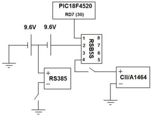
To actuate the ball up to a position to be "pitched" a RS385 motor and scooping arm were used. The motor was hooked up to a 9.6V battery found in the kits. Once activated the arm turns upwards until hitting a static bar. Attached to the bar is a lever switch which sends a pulse to the PIC telling it that a pitch has been thrown. The momentum of the ball would shoot it out of the scoop where a curved ramp would project it onto the play field. The motor is attached to a simple push button so another player can pitch creating a more interactive game. The arm, bar and ramp were made out of scrap sheet metal found in the machine shop.
Electrical Design
PIC Schematic
Circuit Diagram
Sensor
Pitcher and Bat
LED Circuit
Seven Segment Display
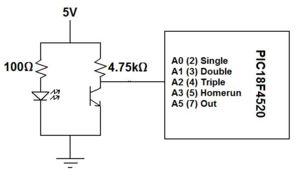
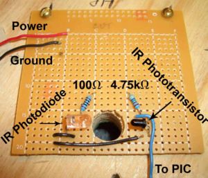
Photodiode/Phototransistor Sensor
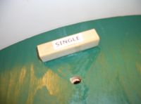
An IR optical sensor was used to detect the ball falling through a hole. The transistor will be receive a large amount of infrared radiation constantly, until a ball falls through. The obstruction will send a pulse to the PIC and either an out, single, double, triple or homerun will be executed.
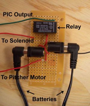
Bat Relay & Power Supplies
In order to power our solenoid and motor we needed external power. We used the 9.6V rechargeable batteries found in the lab kits. The first battery is permanently connected to the pitching motor as well as in series with the second battery. The two batteries in series are connected to the solenoid via a RSB52 relay. When the PIC sends a high pulse to activate the coil the user can then activate the solenoid with the bat button. The PIC only sends a .5 second pulse, which is a little more time then is needed to pitch the ball. The PIC is activated to send this pulse when the pitching arm hits the lever switch located on the stopping bar in the back of the game (See pitching above).
Ideally, when the pitch button is activated it will turn the arm upwards and both activate the switch and pitch the ball. The relay will come on allowing the player to complete the loop on the solenoid with the bat button. Once the half second delay ends the relay closes, which means the user can no longer activate the bat. This way only one swing is allowed per pitch.
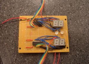
Scoreboard Circuitry
For the scoreboard we used two seven segment displays LTD-4708JS and a HEF 4543B decoder chip for each. We used pins RD0-RD5 and RB0-RB5 on the PIC for the two displays. The connections are the same as those outlined here. The scoreboard also had two LEDs for counting the number of outs.
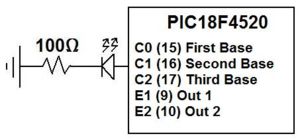
Base and Out LEDs
For the three bases and the two out indicators we used the same bright red LEDs. We attached them in series with a 100 Ohm resistor and sent a signal from the PIC. Once a man was on base, or an out was indicated the PIC would output a digital high signal. Below is an example of a base LED.
PIC Code
General outline of code:
- Detect switch on pitching mechanism to enable bat
- Detect ball dropping through sensors
- Call appropriate function (single, double, triple, home run, or out)
- Update position of baserunners and light up base LEDs
- Display updated score and outs on scoreboard
- Switch teams at three outs
- End game after three innings
Variable and function definitions:
#include <18f4520.h>
#DEVICE ADC=8
#fuses HS,NOLVP,NOWDT,NOPROTECT
#use delay(clock=20000000)

#define FIRSTBASE PIN_C0			//Output to base LEDs
#define SECONDBASE PIN_C1
#define THIRDBASE PIN_C2
#define SINGLE_SENSOR PIN_A0			//Analog input pins for each sensor
#define DOUBLE_SENSOR PIN_A1
#define TRIPLE_SENSOR PIN_A2
#define HR_SENSOR PIN_A3
#define OUT_SENSOR PIN_A5
#define OUT1 PIN_E1       			//Output to scoreboard out LEDs
#define OUT2 PIN_E2
#define BATSWITCH PIN_D7			//Output to enable bat

void singlehit();
void doublehit();
void triplehit();
void homerun();
void out();
void displayscore();

int8 singlesensor, doublesensor, triplesensor, hrsensor, outsensor;
int8 outs=0, innings=0, stopswitch;
int8 team1score=0, remainder1=0, tensdigit1=0;
int8 team2score=0, remainder2=0, tensdigit2=0;
int8 team1=1, team2=0; 				//Team 1 starts at bat

int8 bases=0;
int8 singleadvance[8]={1,3,5,7,9,11,13,15};	//Look at diagram of array initialization
int8 doubleadvance[8]={2,6,10,14,10,14,18,22};
int8 tripleadvance[8]={4,12,12,20,12,20,20,28};
int8 hradvance[8]={8,16,16,24,16,24,24,32};
Main function for baseball game:
void main() {

   setup_adc_ports(AN0_TO_AN5);
   setup_adc(ADC_CLOCK_INTERNAL);

   while(TRUE){

      while(innings<3){     			//Three inning game

         while(team1==1) {  			//Team 1 at bat

	    set_adc_channel(5);
	    delay_us(10);
	    stopswitch = read_adc();

	    if (stopswitch>200){
		output_high(BATSWITCH);
		delay_ms(500);      		//Time for player to swing
		output_low(BATSWITCH);
	    }

	    set_adc_channel(0);			//Read from analog inputs to detect ball
	    delay_us(10);
            singlesensor = read_adc();
	    set_adc_channel(1);
	    delay_us(10);
	    doublesensor = read_adc();
	    set_adc_channel(2);
            delay_us(10);
	    triplesensor = read_adc();
            set_adc_channel(3);
	    delay_us(10);
	    hrsensor = read_adc();
            set_adc_channel(4);
            delay_us(10);
            outsensor = read_adc();

            if (singlesensor > 100) {   	//Call appropriate function depending on where ball dropped
               singlehit();
               delay_ms(1000);			//This delay prevents the program from misreading the sensor, for example,
            }					//if the ball jiggles and triggers the sensor twice in a short period of time
            if (doublesensor > 100) {
               doublehit();
               delay_ms(1000);
            }
            if (triplesensor > 100) {
               triplehit();
               delay_ms(1000);
            }
            if (hrsensor > 100) {
               homerun();
               delay_ms(1000);
            }
            if (outsensor > 100) {
               out();
               delay_ms(1000);
            }

            displayscore();			//Update scoreboard

         }

        while(team2==1) {  			//Team 2 at bat

	    set_adc_channel(5);
	    delay_us(10);
	    stopswitch = read_adc();

	    if (stopswitch>200){
		output_high(BATSWITCH);
		delay_ms(500);
		output_low(BATSWITCH);
	    }

	    set_adc_channel(0);
	    delay_us(10);
            singlesensor = read_adc();
	    set_adc_channel(1);
	    delay_us(10);
	    doublesensor = read_adc();
	    set_adc_channel(2);
            delay_us(10);
	    triplesensor = read_adc();
            set_adc_channel(3);
	    delay_us(10);
	    hrsensor = read_adc();
            set_adc_channel(4);
            delay_us(10);
            outsensor = read_adc();

            if (singlesensor > 100) {
               singlehit();
               delay_ms(1000);
            }
            if (doublesensor > 100) {
               doublehit();
               delay_ms(1000);
            }
            if (triplesensor > 100) {
               triplehit();
               delay_ms(1000);
            }
            if (hrsensor > 100) {
               homerun();
               delay_ms(1000);
            }
            if (outsensor > 100) {
               out();
               delay_ms(1000);
            }

            displayscore();

         }

      innings=innings+1;			//Next inning

   }

   team1score=0;				//New game after three innings
   team2score=0;
   bases=0;
   innings=0;

   }


}
Functions for single, double, triple, home run, and out:
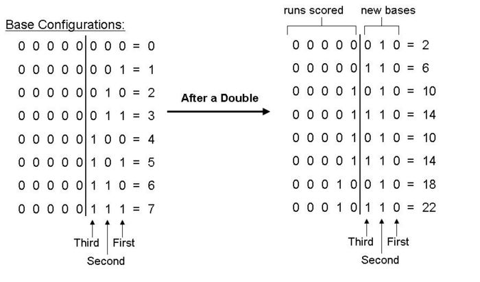
For the single, double, triple, and home run functions we used different arrays that were initialized at the beginning of the program. The values in these arrays are explained through the following diagram:
In this example for a double, the left side of the figure shows the eight possible base configurations. The first three bits represent first, second and third base (a 1 indicates a runner on base). After a double the baserunners advance two bases as shown on the right side of the figure. We kept track of runs scored by using the five bits on the left. At the beginning of the program arrays were initialized for each type of hit. For a double, the initialization would be:
int8 doubleadvance[8]={2,6,10,14,10,14,18,22};
This way we could use the global variable, bases, to call up the appropriate value from each array. To determine the number of runs scored, we simply shifted the bits to the right by three places (>>3). To update the position of the baserunners, we had to clear all the bits except the first three. This was accomplished by shifting the bits to the left five places (<<5) then shifting them to the right by five (>>5) places. The result was the new value for bases.
Single:
void singlehit(){

   int runsadded, basetemp;

   runsadded = singleadvance[bases]>>3;		//Determine run scored
   basetemp=singleadvance[bases]<<5;
   bases=basetemp>>5;				//Update baserunners' positions

   output_C(bases);				//Light up appropriate bases

   if(team1==1){				//Update score
      team1score=team1score+runsadded;
   }
   if(team2==1){
      team2score=team2score+runsadded;
   }

}
Double:
void doublehit() {

   int runsadded, basetemp;

   runsadded = doubleadvance[bases]>>3;
   basetemp=doubleadvance[bases]<<5;
   bases=basetemp>>5;

   output_C(bases);

   if(team1==1){
      team1score=team1score+runsadded;
   }
   if(team2==1){
      team2score=team2score+runsadded;
   }

}
Triple:
void triplehit() {

   int runsadded, basetemp;

   runsadded = tripleadvance[bases]>>3;
   basetemp=tripleadvance[bases]<<5;
   bases=basetemp>>5;

   output_C(bases);

   if(team1==1){
      team1score=team1score+runsadded;
   }
   if(team2==1){
      team2score=team2score+runsadded;
   }

}
Home run:
void homerun() {

   int runsadded, basetemp;

   runsadded = hradvance[bases]>>3;
   basetemp=hradvance[bases]<<5;
   bases=basetemp>>5;

   output_C(bases);

   if(team1==1){
      team1score=team1score+runsadded;
   }
   if(team2==1){
      team2score=team2score+runsadded;
   }

}
Out:
void out() {

   outs=outs+1;

   if (outs==3 && team1==1){     		//Switch to Team 2 at bat
      team1=0;
      team2=1;
      outs=0;
      bases=0;					//Clear the bases
      output_low(FIRSTBASE);
      output_low(SECONDBASE);
      output_low(THIRDBASE);

   }
   if (outs==3 && team2==1){     		//Switch to Team 1 at bat
      team2=0;
      team1=1;
      outs=0;
      bases=0;
      output_low(FIRSTBASE);
      output_low(SECONDBASE);
      output_low(THIRDBASE);

   }

}
Function for scoreboard display:
void displayscore() {

      remainder1 = team1score % 10;
      tensdigit1 = (team1score - remainder1)/10;

      output_b(remainder1 & 15);
      output_high(PIN_B4);			//Activate ones digit
      delay_ms(2);
      output_b(tensdigit1 & 15);
      output_high(PIN_B5);			//Activate tens digit
      delay_ms(2);

      remainder2 = team2score % 10;
      tensdigit2 = (team2score - remainder2)/10;

      output_d(remainder2 & 15);
      output_high(PIN_D4);
      delay_ms(2);
      output_d(tensdigit2 & 15);
      output_high(PIN_D5);
      delay_ms(2);

      if (outs==0 || outs==3){      		//Out LEDs on scoreboard
      output_low(OUT1);
      output_low(OUT2);
      }
      if (outs==1) {
         output_high(OUT1);
      }
      if (outs==2){
         output_high(OUT1);
         output_high(OUT2);
      }

}
Results and Reflections
Overall, our baseball project was successful, the bat performed reliably and with its range of motion it was possible to hit all four targets. The pitching mechanism was effective; however, we did have a few cases where the lever arm would get stuck or the ball would drop out. To improve this the lever arm could be smoothed out and a piece of tubing could replace the metal sheet. This should make the pitching more reliable.
The base LEDs and the scoreboard functioned properly. The four sensors for single, double, triple and home run detected the ball consistently and advanced the baserunners correctly. One major problem we found was that occasionally the program missed reading an out. This is due to the timing of the program, so that when the ball fell through the out sensor the program would not be reading from the analog input at that time. We tried to adjust the 500ms delay when the player can swing (see Code), but the program would still miss reading the sensor. One possible way to fix this is to use an interrupt triggered by a digital input pin.
Originally we intended for the game to pitch automatically using another relay circuit to the pitching motor. The program would then activate the pitching mechanism at random times. We ended up using a button for the pitching because it would be more interactive and allow two people to play against each other.
