Difference between revisions of "Continuously Variable Transmission"
DavidEvitt (talk | contribs) |
DavidEvitt (talk | contribs) |
||
| (13 intermediate revisions by the same user not shown) | |||
| Line 1: | Line 1: | ||
[[image: CVT_system.JPG| |
[[image: CVT_system.JPG|450px|right]] |
||
== Team members == |
== Team members == |
||
| ⚫ | |||
| ⚫ | |||
* David Evitt: Mechanical Engineering, Class of 2009 |
* David Evitt: Mechanical Engineering, Class of 2009 |
||
* Tyler Miller: Electrical Engineering, Class of 2009 |
* Tyler Miller: Electrical Engineering, Class of 2009 |
||
* Raymond Mui: Mechanical Engineering, Class of 2008 |
* Raymond Mui: Mechanical Engineering, Class of 2008 |
||
<br clear=all> |
<br clear=all> |
||
== Overview == |
== Overview == |
||
[[image: CVT_Ratio.JPG|thumb|200px| Low-High Ratio]] |
[[image: CVT_Ratio.JPG|thumb|200px| Low-High Ratio]] |
||
| Line 19: | Line 16: | ||
A CVT is a type of transmission that can smoothly transition between gear ratios. This can be achieved in a variety of ways. We chose to use movable conical pulley halves and a v-belt, similar to the CVTs commonly found on snowmobiles. The conical faces of the pulley halves create a valley that the belt rides in. The belt wedges as far down in the valley as possible, so the distance between the pulleys controls what radius the belt rides at. As the pulley halves move together it forces the belt out of the valley to run at a larger radius, if the pulley halves move further apart the belt will fall down the valley to run at a smaller radius. Two sets of pulley halves work together and move simultaneously to form the transmission. One pulley moves to control the gear ratio, the other pulley adjusts to maintain belt tension. For example if the input pulley halves begin far apart and the output pulley halves begin close together the transmission is in low gear. As the input pulley halves move together, the output pulley halves move apart to maintain constant belt tension, as illustrated in the figure. This motion is a smooth shift from low to high gear, as shown in the [http://www.youtube.com/watch?v=M9bJ_b61E-4 video]. |
A CVT is a type of transmission that can smoothly transition between gear ratios. This can be achieved in a variety of ways. We chose to use movable conical pulley halves and a v-belt, similar to the CVTs commonly found on snowmobiles. The conical faces of the pulley halves create a valley that the belt rides in. The belt wedges as far down in the valley as possible, so the distance between the pulleys controls what radius the belt rides at. As the pulley halves move together it forces the belt out of the valley to run at a larger radius, if the pulley halves move further apart the belt will fall down the valley to run at a smaller radius. Two sets of pulley halves work together and move simultaneously to form the transmission. One pulley moves to control the gear ratio, the other pulley adjusts to maintain belt tension. For example if the input pulley halves begin far apart and the output pulley halves begin close together the transmission is in low gear. As the input pulley halves move together, the output pulley halves move apart to maintain constant belt tension, as illustrated in the figure. This motion is a smooth shift from low to high gear, as shown in the [http://www.youtube.com/watch?v=M9bJ_b61E-4 video]. |
||
A variable ratio transmission |
A variable ratio transmission has a variety of applications. With a fixed gear ratio, the output speed is a constant multiple of the input speed. This means that as the output speed increases the input speed must also increase. In a vehicle application this means that the engine speed changes greatly as the vehicle accelerates. If the gear ratio is variable the input can remain at constant speed as the output speed increases. In vehicle terms, the engine speed can be held constant while the vehicle accelerates. This is helpful because the engine can always operate at peak power for maximum acceleration, or at maximum efficiency. The Formula SAE team is working toward implementing a CVT on their next competition vehicle to take advantage of this property. This proof of concept prototype is the first step towards that goal. |
||
More about CVTs can be found in the [[Continuously_Variable_Transmission#Further_Reading|further reading section]]. |
More about CVTs can be found in the [[Continuously_Variable_Transmission#Further_Reading|further reading section]]. |
||
This wiki page documents the mechanical and electrical systems, the code, and our reflections on the project. |
This wiki page documents the mechanical and electrical systems, the code, and our reflections on the project. |
||
| ⚫ | |||
== |
== Mechanical Design == |
||
=== System Operation === |
|||
[[image: |
[[image:CVT_Overview.jpg|thumb|200px|CVT assembly]] |
||
[[image:CVT_Moveable_Pulley.jpg|thumb|200px|Movable pulley detail]] |
|||
Our CVT shown to the right was constructed in the Ford Building machine shop |
Our CVT shown to the right was constructed in the Ford Building machine shop. It consists of two pulley assemblies. Each pulley assembly has one half fixed to the shaft, the other half is able to translate along the shaft, but is prevented from rotating by the torque transfer plate, which is fixed to the shaft. The movable pulley slides on bushings and rolls on the torque transfer plate bearings so it is free to move, even under load. The position of the movable pulley is determined by the pulley actuator, which is controlled by the lead screw. Three Pittman GM8224 motors actuate the system. One spins the input shaft, the other two control the lead screws setting pulley position. |
||
<br clear=all> |
|||
=== Pulley Control === |
|||
| ⚫ | |||
[[image:CVT_Limit_Switch.jpg|thumb|200px|Limit Switch]] |
|||
The input and output pulleys serve different functions which are reflected in the control hardware. The input pulley sets the gear ratio, the output pulley maintains belt tension. The input pulley actuation system is rigid, enforcing the pulley position commanded by the controller. The output actuation system has compliance built in with springs, allowing flexibility to maintain a near constant belt tension. |
|||
We used three Pittman GM8224 motors to control the apparatus. Two motors function to drive the lead screw for each of the two pulleys. These connect to the shafts by two flexible connector hoses to allow a bit of play. We used the third Pittman running at the full 24 volts to simulate the constant speed input running at max efficiency. |
|||
The control motors turn a lead screw that pushes a drive nut. That drive nut slides the actuator frame along the guide shafts, which adjusts the pulley actuator, controlling pulley position. The wide actuator frame is necessary to resist the moment from the cantilever pulley actuator and not bind. In the case of the output actuator, the drive plate floats in the actuator frame on springs. As the gear ratio changes the output lead screw control motor turns in the proper direction compressing the springs, which in turn applies belt tension, until the limit switch is depressed at which point the lead screw stops. As the input pulley continues to shift the springs keep adjusting the position of the output pulley until the limit switch opens again. The lead screw then moves until the switch is again closed. The net result is that the output control screw moves in small steps and the spring force keeps even belt tension. |
|||
<br clear=all> |
<br clear=all> |
||
=== |
=== Flex Coupling === |
||
[[image:CVT_Flex_Coupling.jpg|thumb|200px|Flex Coupling]] |
|||
Simple flex couplings to connect the motor and control shafts were developed for this prototype. They consist of flexible tubing pressed over matching pins as seen in the figure at right and have the following benefits: |
|||
To simulate the gear change, we have a dial hooked onto a potentiometer as the user interface. The changing resistance controls the gear ratio from low to high. The PIC code then reads the voltage and spins the two motors controlling the lead screws to change the gear ratio accordingly. As the lead screws move, they drive the pulley half along at a controlled rate, adjusting the pulley width. As the distance between halves decreases, the radius increases. The converse is true. |
|||
* Significant misalignment in any direction can be accommodated. |
|||
* The stiffness of the joint can be adjusted with the number of pin pairs and tubing properties. |
|||
* They provide overload protection. At a certain torque the tubing segments will rip or pop of the pins to break free. |
|||
The design can readily be adapted to other applications and may be useful for other student projects as a low cost option. |
|||
For each revolution of the Pittman motor, the lead screw will advance the pulley half by a tenth of an inch forward. The pulley width will only vary by 1 inch from switching from low to high radius. As the pulley half decreases, the radius will change from 0.866 in to 2.44 in. The driver pulley will tighten the v-belt as it increases the radius, so the driven pulley will have to react accordingly. |
|||
=== |
=== Mechanical Part List === |
||
<table border=1> |
|||
<tr><th>Part</th><th>Part No.</th><th>Qty</th><th>Vendor</th><th>Price (Total)</th></tr> |
|||
[[image:CVT_limit_switches.jpg|thumb|300px|Limit switches on driven pulley]] |
|||
<tr><td>Pittman 24V DC motor</td><td>GM8224</td><td>3</td><td>Lab</td><td>-</td></tr> |
|||
<tr><td>Shoulder Screw</td><td>91259A535</td><td>8</td><td>[http://www.mcmaster.com McMaster]</td><td>$6.56</td></tr> |
|||
<tr><td>1/4" bearing</td><td>60355K33</td><td>8</td><td>[http://www.mcmaster.com McMaster]</td><td>$39.84</td></tr> |
|||
<tr><td>3/8" bearing</td><td>60355K35</td><td>4</td><td>[http://www.mcmaster.com McMaster]</td><td>$20.68</td></tr> |
|||
<tr><td>3/4" bearing</td><td>60355K38</td><td>4</td><td>[http://www.mcmaster.com McMaster]</td><td>$33.40</td></tr> |
|||
<tr><td>Thrust bearing</td><td>6655K22</td><td>2</td><td>[http://www.mcmaster.com McMaster]</td><td>$10.96</td></tr> |
|||
<tr><td>SAE 841 1/2" bushing</td><td>6391K212</td><td>10</td><td>[http://www.mcmaster.com McMaster]</td><td>$6.50</td></tr> |
|||
<tr><td>SAE 814 3/4" bushing 1" long</td><td>6391K259</td><td>2</td><td>[http://www.mcmaster.com McMaster]</td><td>$2.98</td></tr> |
|||
<tr><td>SAE 814 3/4" bushing 2" long</td><td>6391K269</td><td>2</td><td>[http://www.mcmaster.com McMaster]</td><td>$8.40</td></tr> |
|||
<tr><td>1/2" steel drive shaft</td><td>1346K17</td><td>4</td><td>[http://www.mcmaster.com McMaster]</td><td>$25.84</td></tr> |
|||
<tr><td>3/4" steel drive shaft</td><td>1346K31</td><td>4</td><td>[http://www.mcmaster.com McMaster]</td><td>$19.12</td></tr> |
|||
<tr><td>spring</td><td>9620K57</td><td>4</td><td>[http://www.mcmaster.com McMaster]</td><td>$17.68</td></tr> |
|||
<tr><td>1/2"-10 Acme threaded rod</td><td>98935A823</td><td>1</td><td>[http://www.mcmaster.com McMaster]</td><td>$7.12</td></tr> |
|||
<tr><td>Bronze 1/2"-10 Acme nut</td><td>1343K134</td><td>2</td><td>[http://www.mcmaster.com McMaster]</td><td>$72.24</td></tr> |
|||
<tr><td>Misc. fasteners and stock</td><td>-</td><td>-</td><td>Shop</td><td>-</td></tr> |
|||
</table> |
|||
<br clear=all> |
|||
| ⚫ | |||
Two limit switches rest on the second pulley provide a means of controlling the movement of the driven pulley. |
|||
=== Control System Overview === |
|||
Our second pulley half uses another Pittman motor with the same lead screw setup to adjust the width. However, to assist in moving the halves, we implemented springs to push the pulley halves together to assist maintaining belt tension. A metal fork resting on the moving support for the pulley half triggers the switches if the pulley moves too far. The triggered switches send a signal to either pin RD0 or RD1 of the PIC. As it triggers, the PIC stops the driven pulley half from moving further. The springs on the guide shafts of the driven pulley then correct the pulley width as needed until the fork no longer triggers either switch. |
|||
The control system for this prototype was intended to operate as follows. A potentiometer sends a 0-5V signal to the A to D converter on the PIC. Zero V corresponds to low gear, five V corresponds to high gear. The input voltage is scaled to correspond to the desired encoder counts of the input control motor. As the pot is swept from low to high the input pulley shifts from low gear position to high gear position. The output pulley is given a direction to turn, based on the shift direction. Belt tension is maintained by the limit switches as explained [[Continuously_Variable_Transmission#Pulley_Control|above]]. |
|||
<br clear=all> |
<br clear=all> |
||
| ⚫ | |||
| ⚫ | |||
| ⚫ | |||
[[image:CVT_circuit.jpg|thumb|200px|Completed Circuit]] |
|||
Refer to the circuit diagram at right for details of the electrical system. |
|||
| ⚫ | |||
To control the two Pittman motors, we used |
To control the two Pittman motors, we used the two PIC PWM outputs going through the SN74HC04N inverter chip to the L298N H-bridge chip, one for each motor. To keep track of the input pulley encoder counts we used [[Quadrature decoding in hardware, or just counters|quadrature decoding]] with the LS7183 decoder chip going to the PIC clock inputs. |
||
'''''Warning''''' there was a problem with either the wiring diagram or the actual physical circuit that fried a bunch of components and ultimately prevented us from using implementing the planned control strategy in the time available. Use with caution and verify on your own. |
|||
| ⚫ | |||
A schematic of the circuit is presented to the right. |
|||
| ⚫ | |||
| ⚫ | |||
The completed circuit setup can be viewed on the right. |
|||
=== Electrical Part List === |
|||
<table border=1> |
|||
<tr><th>Part</th><th>Part No.</th><th>Qty</th><th>Vendor</th></tr> |
|||
<tr><td>PIC and board</td><td>-</td><td>1</td><td>Lab</td></tr> |
|||
<tr><td>H-bridge</td><td>L298N</td><td>2</td><td>Lab</td></tr> |
|||
<tr><td>Inverter</td><td>SN74HC04N</td><td>1</td><td>Lab</td></tr> |
|||
<tr><td>Quadrature decoder</td><td>LS7183</td><td>1</td><td>Lab</td></tr> |
|||
<tr><td>5V power supply</td><td>-</td><td>1</td><td>Lab</td></tr> |
|||
<tr><td>24V power supply</td><td>-</td><td>1</td><td>Lab</td></tr> |
|||
</table> |
|||
<br clear=all> |
<br clear=all> |
||
| Line 70: | Line 105: | ||
The PIC reads an input voltage reading from the potentiometer from pin RA0. This value is compared to the upper and lower bounds governing the pulley's widths to determine whether the pulley needs to move farther or closer together. We then use quadrature decoding to keep track of the counts, thereby tracking the number of rotations. With the 10:1 gear ratio (10 revolutions per 1 in of travel), we also know how far it has moved. We modified the quadrature hardware [http://peshkin.mech.northwestern.edu/pic/code/QuadratureHard/ code ] available from the example code page to perform this task. |
The PIC reads an input voltage reading from the potentiometer from pin RA0. This value is compared to the upper and lower bounds governing the pulley's widths to determine whether the pulley needs to move farther or closer together. We then use quadrature decoding to keep track of the counts, thereby tracking the number of rotations. With the 10:1 gear ratio (10 revolutions per 1 in of travel), we also know how far it has moved. We modified the quadrature hardware [http://peshkin.mech.northwestern.edu/pic/code/QuadratureHard/ code ] available from the example code page to perform this task. |
||
The code for the entire setup can be found here. |
The code for the entire setup can be found here. '''''Note''''' due to the electrical problem described [[Continuously_Variable_Transmission#Circuit|above]] the code is untested. |
||
* [[media:CVTcontrolcode.c|CVTcontrolcode.c]] |
* [[media:CVTcontrolcode.c|CVTcontrolcode.c]] |
||
<br clear=all> |
|||
== Results == |
== Results and Reflections == |
||
Despite the trouble with the electrical system we were still able to learn a great deal from this prototype. |
|||
Unfortunately, due to technical errors and circuit component failure (namely frying three PICs along with other melted components), we were not able to implement the PIC control for the two pulleys. To demonstrate the apparatus, we implemented manual control of the two Pittmans using switches to control the pulley widths. The demonstration showed that the system functions well mechanically. Manual control illustrated the need for feedback control for this system, as the transitions from low to high gear required a nonlinear shift in the pulley radii. |
|||
With further work on the circuits and controls, we hope to get the CVT working as intended with PIC control. |
|||
To demonstrate the system, we implemented manual control of pulley position using switches. The demonstration showed that the system functions well mechanically but has opportunities for improvement. Even with the wide support of the pulley actuator frame the clamping force on the belt was low. As the lead screw forced the pulley halves together the actuator frame started to cock on the guide shafts and bind, limiting what belt tension could be achieved. In the next iteration it is essential that the pulley actuation be concentric to the input/output shafts which will enable much higher belt clamping forces to be generated which is necessary for transmitting power. In the future much more time will be scheduled for debugging the electrical system to ensure there is enough time to develop and fine tune the program. |
|||
<br clear=all> |
|||
== Further Reading == |
== Further Reading == |
||
| Line 85: | Line 121: | ||
* http://auto.howstuffworks.com/cvt.htm |
* http://auto.howstuffworks.com/cvt.htm |
||
* http://cars.about.com/od/thingsyouneedtoknow/a/CVT.htm |
* http://cars.about.com/od/thingsyouneedtoknow/a/CVT.htm |
||
<br clear=all> |
|||
Latest revision as of 07:02, 21 March 2008
Team members
- David Evitt: Mechanical Engineering, Class of 2009
- Tyler Miller: Electrical Engineering, Class of 2009
- Raymond Mui: Mechanical Engineering, Class of 2008
Overview
The goal of this project was to create an electronically controlled, belt-driven, continuously variable transmission (CVT).
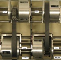
A CVT is a type of transmission that can smoothly transition between gear ratios. This can be achieved in a variety of ways. We chose to use movable conical pulley halves and a v-belt, similar to the CVTs commonly found on snowmobiles. The conical faces of the pulley halves create a valley that the belt rides in. The belt wedges as far down in the valley as possible, so the distance between the pulleys controls what radius the belt rides at. As the pulley halves move together it forces the belt out of the valley to run at a larger radius, if the pulley halves move further apart the belt will fall down the valley to run at a smaller radius. Two sets of pulley halves work together and move simultaneously to form the transmission. One pulley moves to control the gear ratio, the other pulley adjusts to maintain belt tension. For example if the input pulley halves begin far apart and the output pulley halves begin close together the transmission is in low gear. As the input pulley halves move together, the output pulley halves move apart to maintain constant belt tension, as illustrated in the figure. This motion is a smooth shift from low to high gear, as shown in the video.
A variable ratio transmission has a variety of applications. With a fixed gear ratio, the output speed is a constant multiple of the input speed. This means that as the output speed increases the input speed must also increase. In a vehicle application this means that the engine speed changes greatly as the vehicle accelerates. If the gear ratio is variable the input can remain at constant speed as the output speed increases. In vehicle terms, the engine speed can be held constant while the vehicle accelerates. This is helpful because the engine can always operate at peak power for maximum acceleration, or at maximum efficiency. The Formula SAE team is working toward implementing a CVT on their next competition vehicle to take advantage of this property. This proof of concept prototype is the first step towards that goal.
More about CVTs can be found in the further reading section.
This wiki page documents the mechanical and electrical systems, the code, and our reflections on the project.
Mechanical Design
System Operation
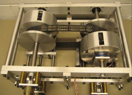
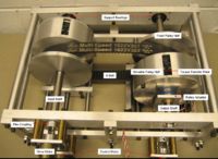
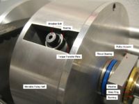
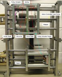
Our CVT shown to the right was constructed in the Ford Building machine shop. It consists of two pulley assemblies. Each pulley assembly has one half fixed to the shaft, the other half is able to translate along the shaft, but is prevented from rotating by the torque transfer plate, which is fixed to the shaft. The movable pulley slides on bushings and rolls on the torque transfer plate bearings so it is free to move, even under load. The position of the movable pulley is determined by the pulley actuator, which is controlled by the lead screw. Three Pittman GM8224 motors actuate the system. One spins the input shaft, the other two control the lead screws setting pulley position.
Pulley Control
The input and output pulleys serve different functions which are reflected in the control hardware. The input pulley sets the gear ratio, the output pulley maintains belt tension. The input pulley actuation system is rigid, enforcing the pulley position commanded by the controller. The output actuation system has compliance built in with springs, allowing flexibility to maintain a near constant belt tension.
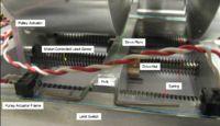
The control motors turn a lead screw that pushes a drive nut. That drive nut slides the actuator frame along the guide shafts, which adjusts the pulley actuator, controlling pulley position. The wide actuator frame is necessary to resist the moment from the cantilever pulley actuator and not bind. In the case of the output actuator, the drive plate floats in the actuator frame on springs. As the gear ratio changes the output lead screw control motor turns in the proper direction compressing the springs, which in turn applies belt tension, until the limit switch is depressed at which point the lead screw stops. As the input pulley continues to shift the springs keep adjusting the position of the output pulley until the limit switch opens again. The lead screw then moves until the switch is again closed. The net result is that the output control screw moves in small steps and the spring force keeps even belt tension.
Flex Coupling
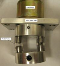
Simple flex couplings to connect the motor and control shafts were developed for this prototype. They consist of flexible tubing pressed over matching pins as seen in the figure at right and have the following benefits:
- Significant misalignment in any direction can be accommodated.
- The stiffness of the joint can be adjusted with the number of pin pairs and tubing properties.
- They provide overload protection. At a certain torque the tubing segments will rip or pop of the pins to break free.
The design can readily be adapted to other applications and may be useful for other student projects as a low cost option.
Mechanical Part List
| Part | Part No. | Qty | Vendor | Price (Total) |
|---|---|---|---|---|
| Pittman 24V DC motor | GM8224 | 3 | Lab | - |
| Shoulder Screw | 91259A535 | 8 | McMaster | $6.56 |
| 1/4" bearing | 60355K33 | 8 | McMaster | $39.84 |
| 3/8" bearing | 60355K35 | 4 | McMaster | $20.68 |
| 3/4" bearing | 60355K38 | 4 | McMaster | $33.40 |
| Thrust bearing | 6655K22 | 2 | McMaster | $10.96 |
| SAE 841 1/2" bushing | 6391K212 | 10 | McMaster | $6.50 |
| SAE 814 3/4" bushing 1" long | 6391K259 | 2 | McMaster | $2.98 |
| SAE 814 3/4" bushing 2" long | 6391K269 | 2 | McMaster | $8.40 |
| 1/2" steel drive shaft | 1346K17 | 4 | McMaster | $25.84 |
| 3/4" steel drive shaft | 1346K31 | 4 | McMaster | $19.12 |
| spring | 9620K57 | 4 | McMaster | $17.68 |
| 1/2"-10 Acme threaded rod | 98935A823 | 1 | McMaster | $7.12 |
| Bronze 1/2"-10 Acme nut | 1343K134 | 2 | McMaster | $72.24 |
| Misc. fasteners and stock | - | - | Shop | - |
Electrical and Control System
Control System Overview
The control system for this prototype was intended to operate as follows. A potentiometer sends a 0-5V signal to the A to D converter on the PIC. Zero V corresponds to low gear, five V corresponds to high gear. The input voltage is scaled to correspond to the desired encoder counts of the input control motor. As the pot is swept from low to high the input pulley shifts from low gear position to high gear position. The output pulley is given a direction to turn, based on the shift direction. Belt tension is maintained by the limit switches as explained above.
Circuit
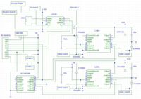
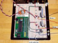
Refer to the circuit diagram at right for details of the electrical system.
To control the two Pittman motors, we used the two PIC PWM outputs going through the SN74HC04N inverter chip to the L298N H-bridge chip, one for each motor. To keep track of the input pulley encoder counts we used quadrature decoding with the LS7183 decoder chip going to the PIC clock inputs.
Warning there was a problem with either the wiring diagram or the actual physical circuit that fried a bunch of components and ultimately prevented us from using implementing the planned control strategy in the time available. Use with caution and verify on your own.
Electrical Part List
| Part | Part No. | Qty | Vendor |
|---|---|---|---|
| PIC and board | - | 1 | Lab |
| H-bridge | L298N | 2 | Lab |
| Inverter | SN74HC04N | 1 | Lab |
| Quadrature decoder | LS7183 | 1 | Lab |
| 5V power supply | - | 1 | Lab |
| 24V power supply | - | 1 | Lab |
Programming
The PIC reads an input voltage reading from the potentiometer from pin RA0. This value is compared to the upper and lower bounds governing the pulley's widths to determine whether the pulley needs to move farther or closer together. We then use quadrature decoding to keep track of the counts, thereby tracking the number of rotations. With the 10:1 gear ratio (10 revolutions per 1 in of travel), we also know how far it has moved. We modified the quadrature hardware code available from the example code page to perform this task.
The code for the entire setup can be found here. Note due to the electrical problem described above the code is untested.
Results and Reflections
Despite the trouble with the electrical system we were still able to learn a great deal from this prototype.
To demonstrate the system, we implemented manual control of pulley position using switches. The demonstration showed that the system functions well mechanically but has opportunities for improvement. Even with the wide support of the pulley actuator frame the clamping force on the belt was low. As the lead screw forced the pulley halves together the actuator frame started to cock on the guide shafts and bind, limiting what belt tension could be achieved. In the next iteration it is essential that the pulley actuation be concentric to the input/output shafts which will enable much higher belt clamping forces to be generated which is necessary for transmitting power. In the future much more time will be scheduled for debugging the electrical system to ensure there is enough time to develop and fine tune the program.
Further Reading
More details regarding the operation of a CVT, along with various forms of CVTs
