Difference between revisions of "Controlling a seven segment display"
EricNickel (talk | contribs) |
EricNickel (talk | contribs) |
||
| Line 68: | Line 68: | ||
===Decoder=== |
===Decoder=== |
||
The decoder used in this demonstration was the [http://www.standardics.nxp.com/products/hef/datasheet/hef4543b.pdf HEF 4543B]. It receives a 4-bit binary input as an input and outputs seven logic pins which correspond to the respective segments of a 7-segment display unit. Some display units require that the inputs be logic low to set a segment active. To achieve this, the chip has a phase input pin which will invert the outputs when the pin is set high. |
The decoder used in this demonstration was the [http://www.standardics.nxp.com/products/hef/datasheet/hef4543b.pdf HEF 4543B]. It receives a 4-bit binary input as an input and outputs seven logic pins which correspond to the respective segments of a 7-segment display unit. Some display units require that the inputs be logic low to set a segment active. To achieve this, the chip has a phase input pin which will invert the outputs when the pin is set high. There is also a Blanking pin which will inhibit outputs, ensuring a blank display when set high. For more information regarding this pin, click on the chip name to access the data sheet or [http://www.standardics.nxp.com/products/hef/datasheet/hef4543b.pdf Click Here]. |
||
===Circuit Wiring=== |
===Circuit Wiring=== |
||
Revision as of 14:35, 5 February 2008
Original Assignment
In this project you will use your PIC to display numbers on a seven-segment display.
Overview
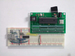
In this example, we will be using PIC 18F4520 to control a double digit 7-segment display LTD-4708JS. A few notes about using this display is that it is only designed to display one unit at a time, so when trying to use both digits, you have to use an ISR to switch between the two digits to create the illusion that both are on simultaneously.
Now, since there are 7 segments, one would assume that you would need 7 outputs from the PIC to display 1 digit. But it is very wasteful to use outputs from the PIC for just displaying like this, so we will be using a chip (HEF 4543B) that will take 4-bits and convert it to the 7-bit output for the 7-segment display.
If you want to display a decimal, this particular 7-segment display will allow you to do so. However, it will take up another output from your PIC.
Finally, if you are planning on displaying more than one digit, you will need an extra bit for every digit that you want to display.
Circuit
There are three primary elements required for a circuit involving a 7-segment display.
The elements are:
1) the 7-segment display
2) the controller (in this case the PIC)
3) the decoder
The 7-segment display used in this demonstration was the LTD-4708JS which can display 2 digits with trailing decimal points. The controller was the PIC 18F4520. The decoder used was the HEF 4543B which takes one 4-bit binary input and converts it to the appropriate 7 logic outputs to drive the 7-segment display.
7-Segment Display
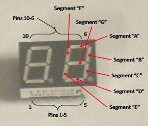
The LTD-4708JS 7-segment display has 10 pins. Seven pins correspond to the seven LED segments, one pin corresponds to the decimal point, and two pins select which digit is being activated. Both digits can be activated simultaneously, however they would not be able to display indepent digits in such a manner. To achieve multi-digit display, the digits must alternate back and forth at a rate preferably greater than 45 Hz for a complete cycle of display (approximately the flicker fusion frequency for the human eye, allowing it to appear that all displayed digits are on continuously).
The LTD-4708JS has 10 pins and they are designated as follows:
Pin 1: Segment "C"
Pin 2: Decimal Point
Pin 3: Segment "E"
Pin 4: Select pin for the second digit
Pin 5: Segment "D"
Pin 6: Segment "F"
Pin 7: Segment "G"
Pin 8: Segment "B"
Pin 9: Select pin for the first digit
Pin 10: Segment "A"
note to self: I need to revise the image with labels to the segments and show the order of pins.
Controller
The controller used in this demonstration was the PIC 18F4520. The demonstration outputs were the digital output pins D0-D3 representing the output number in binary form. The PIC was not used to control which digit was used by the display (the display was hardwired instead to display only one digit). For a multiple-digit display a multiplexer could be used to decode a binary output from the PIC specifying the desired active display digit while the PIC outputs the appropriate digit on the data pins, although there is an upper limit to the number of digits which can be output while retaining a display frequency of greater than 45 Hz which is dependent on the time between calls of the ISR used to display a digit. At 50 Hz each digit must be displayed every 20ms, so if the ISR is called every 4ms, then at most 5 digits may be displayed.
Decoder
The decoder used in this demonstration was the HEF 4543B. It receives a 4-bit binary input as an input and outputs seven logic pins which correspond to the respective segments of a 7-segment display unit. Some display units require that the inputs be logic low to set a segment active. To achieve this, the chip has a phase input pin which will invert the outputs when the pin is set high. There is also a Blanking pin which will inhibit outputs, ensuring a blank display when set high. For more information regarding this pin, click on the chip name to access the data sheet or Click Here.
Circuit Wiring
More to come . . .

