Difference between revisions of "PIC MCUs: 4520 Board"
From Mech
Jump to navigationJump to search| Line 4: | Line 4: | ||
==Board Layout== |
==Board Layout== |
||
[[Image:4520boardtopwikidiag.jpg|right]] |
[[Image:4520boardtopwikidiag.jpg|right]] |
||
<br> |
<br><br><br><br> |
||
{| border="1" cellspacing="2" cellpadding="6" align="center" |
{| border="1" cellspacing="2" cellpadding="6" align="center" |
||
|- |
|- |
||
Revision as of 13:43, 29 June 2007
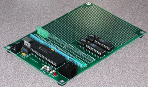
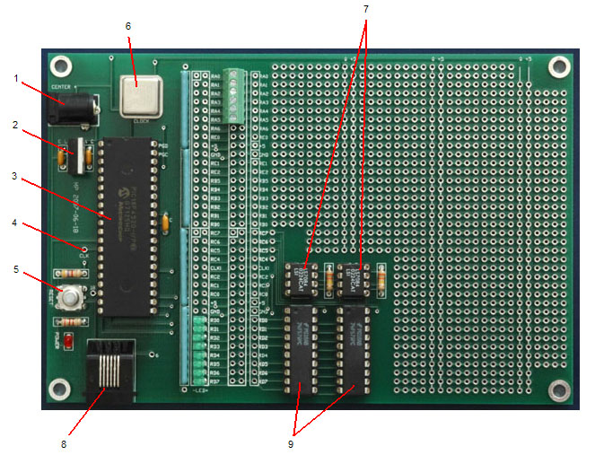
The 4520 Board is designed to be a basic platform in which all comunication and power connections to a PIC18F4520 (the PIC MCU that the board is centered around) are pre-connected, but has otherwise been left open for prototyping. Some of the features of the 4520 Board are shown below.
Board Layout
| 4520 Board Components | |
|---|---|
| 1 | Power supply connector |
| 2 | Voltage regulator |
| 3 | PIC18F4520 microcontroller |
| 4 | Clock signal |
| 5 | Reset/Master Clear button |
| 6 | Clock oscillator |
| 7 | Quadrature clock converters |
| 8 | 6-Pin modular communication port |
| 9 | Tri-state up/down counters |

