Difference between revisions of "Pulse Width Modulation"
m |
|||
| (9 intermediate revisions by 2 users not shown) | |||
| Line 1: | Line 1: | ||
To control the speed of the motor, the switches of an H-bridge are opened and closed at different rates in order to apply different |
To control the speed of the motor, the switches of an H-bridge are opened and closed at different rates in order to apply different |
||
average voltages across the motor. This technique is called <B>pulse width modulation</B>. Let's look at the following diagrams: |
average voltages across the motor. This technique is called <B>pulse width modulation</B> (PWM). Let's look at the following diagrams: |
||
{| |
{| |
||
| Line 15: | Line 15: | ||
Pulse-Width Ratio = <math>\begin{matrix}\frac{t_{on}}{t_{period}}\end{matrix}</math> |
Pulse-Width Ratio = <math>\begin{matrix}\frac{t_{on}}{t_{period}}\end{matrix}</math> |
||
of the voltage applied across its terminals. |
of the voltage applied across its terminals. |
||
The PWM signal can be used to drive an H-bridge to control the direction of the motor. See [http://www.mcmanis.com/chuck/robotics/tutorial/h-bridge/index.html this page] for a nice tutorial, or this [[media:L293.pdf|L293 H-bridge data sheet]] to learn more about H-bridges. |
|||
If the motor only has to turn in 1 direction, we can just use a |
|||
half bridge: |
half bridge: |
||
[[image:half_b.jpg|300px]] |
[[image:half_b.jpg|300px]] |
||
The diode is there because the inductance of the motor does not want the current through the motor to change instantaneously. (Remember that the voltage across an inductor is equal to <math>v=L di/dt</math>, so an instantaneous change in <math>i</math> means an infinite <math>di/dt</math>, resulting in infinite voltage, at least theoretically.) If the motor has current flowing through it, and then we open a switch, the diode provides a path for current to continue to flow through the motor as the energy of the motor is gracefully dissipated through the resistance of the motor (and the diode). This prevents a large voltage transient (an "inductive kick") that could damage your electronics. When a diode is used this way it is called a ''flyback diode''. Such a diode should be capable of carrying large currents and switching on and off quickly. See more at [[Diodes and Transistors]]. |
|||
There are different ways to control the speed of a DC motor: |
There are different ways to control the speed of a DC motor: |
||
# switching from full positive to full negative |
# switching from full positive to full negative |
||
# full positive to open |
# full positive to open |
||
# full negative to open |
# full negative to open |
||
# braking by shorting |
# braking by shorting |
||
# free wheeling by leaving the circuit open. |
# free wheeling by leaving the circuit open. |
||
| ⚫ | |||
| ⚫ | |||
| ⚫ | |||
| ⚫ | |||
| ⚫ | |||
For a practical circuit that controls a DC motor using PWM, see the [[PIC PWM Motor Driver]]. |
|||
| ⚫ | |||
the heat away. One of the ways to do this is to connect pins of the L293 to piece of metal or copper. |
|||
Latest revision as of 15:20, 6 January 2007
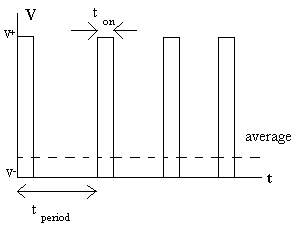
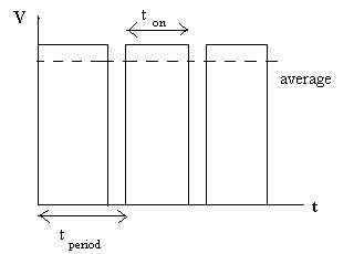
To control the speed of the motor, the switches of an H-bridge are opened and closed at different rates in order to apply different average voltages across the motor. This technique is called pulse width modulation (PWM). Let's look at the following diagrams:

|

|
In the above diagrams, V is the voltage across the motor and t is time. By switching quickly, we can create an average voltage across across the motor. The speed of the motor can be adjusted by changing the pulse-width ratio:
Pulse-Width Ratio =
of the voltage applied across its terminals.
The PWM signal can be used to drive an H-bridge to control the direction of the motor. See this page for a nice tutorial, or this L293 H-bridge data sheet to learn more about H-bridges.
If the motor only has to turn in 1 direction, we can just use a half bridge:
The diode is there because the inductance of the motor does not want the current through the motor to change instantaneously. (Remember that the voltage across an inductor is equal to , so an instantaneous change in means an infinite , resulting in infinite voltage, at least theoretically.) If the motor has current flowing through it, and then we open a switch, the diode provides a path for current to continue to flow through the motor as the energy of the motor is gracefully dissipated through the resistance of the motor (and the diode). This prevents a large voltage transient (an "inductive kick") that could damage your electronics. When a diode is used this way it is called a flyback diode. Such a diode should be capable of carrying large currents and switching on and off quickly. See more at Diodes and Transistors.
There are different ways to control the speed of a DC motor:
- switching from full positive to full negative
- full positive to open
- full negative to open
- braking by shorting
- free wheeling by leaving the circuit open.
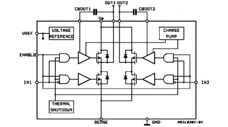
One of the possibilities is to use a full H-bridge chip, such as the L6201 shown below:
When using a integrated chip, one of the concerns is heat sinking. It is because there are lots of power dissipation and we need to take the heat away. Usually, these chips come with some way to attach to piece of metal or copper (a heatsink).
For a practical circuit that controls a DC motor using PWM, see the PIC PWM Motor Driver.


