Difference between revisions of "Monkeybot"
Nelson Rosa (talk | contribs) |
|||
| (2 intermediate revisions by 2 users not shown) | |||
| Line 1: | Line 1: | ||
[[Image:monkeybot_pic|thumb|right|350px| |
[[Image:monkeybot_pic|thumb|right|350px|Monkeybot]] |
||
<br> |
<br> |
||
<br> |
<br> |
||
| Line 26: | Line 26: | ||
==Simulation== |
==Simulation== |
||
We developed a simulation that shows how the brachiating robot would ideally climb given a closed-loop control law that continuously pumps energy into the system. The simulation assumes point mass objects (red dots), viscous friction at the revolute joints, and an input forcing function at the motor joint (middle red dot). The simulation was done in Mathematica 7.0 and the code is hosted as a [http://code.google.com/p/hoppingrobot/ Google code project]. |
We developed a simulation that shows how the brachiating robot would ideally climb given a closed-loop control law that continuously pumps energy into the system. The simulation assumes point mass objects (red dots), viscous friction at the revolute joints, and an input forcing function at the motor joint (middle red dot). The simulation was done in Mathematica 7.0 and the code is hosted as a [http://code.google.com/p/hoppingrobot/ Google code project]. |
||
[[Media:monkeybot-sim.swf]] |
|||
==Control Method== |
==Control Method== |
||
| Line 75: | Line 73: | ||
===Design Considerations=== |
===Design Considerations=== |
||
The two links, made of 1/8” thick acrylic, create the body of the robot and create a mount for both bearings and the motor. The thickness and the material was chosen to minimize weight, and thus the torque required to swing the robot. The links were produced using a laser cutter. The rotational ball bearings mount on the links and hold the magnets, allowing the robot to swing around a fixed point. The encoders are mounted above the magnets on a bridge, so that they are capable of measuring the rotation of the link around the magnet. |
The two links, made of 1/8” thick acrylic, create the body of the robot and create a mount for both bearings and the motor. The thickness and the material was chosen to minimize weight, and thus the torque required to swing the robot. The links were produced using a [[laser cutter | Laser Cutter]]. The rotational ball bearings mount on the links and hold the magnets, allowing the robot to swing around a fixed point. The encoders are mounted above the magnets on a bridge, so that they are capable of measuring the rotation of the link around the magnet. |
||
The Pittman motor was chosen to provide enough torque to the links to overcome friction. The gear head is also needed to get the necessary torque. With the gear head, the Pittmann is capable of providing 2.1 Nm of torque, which is more than enough for this application. However, the motor is rather large and thus increases the overall weight of the system. |
The Pittman motor was chosen to provide enough torque to the links to overcome friction. The gear head is also needed to get the necessary torque. With the gear head, the Pittmann is capable of providing 2.1 Nm of torque, which is more than enough for this application. However, the motor is rather large and thus increases the overall weight of the system. |
||
Latest revision as of 11:11, 20 March 2012
Team Members
Nathan Henry - Senior, Mechanical Engineering
Nelson Rosa - Ph.D Student, Mechanical Engineering
Overview
The goal of this project was to create a brachiating robot capable of swinging itself side to side or climbing. This two link robot has electro-magnets on each end and a DC motor at the pivot. With one magnet on, the robot swings under gravity and is aided by a input torque from the motor. This torque allows the swinging robot to overcome friction and pump energy into the system. Once the swinging arm has enough energy, the second magnet reaches a point at the same height or above the first magnet. At this point, the second magnet is turned on the motor is turned off. Now the process is repeated, swinging on the second magnet.
We attempted to control the motor using both a closed loop control, with rotary encoders, and an open loop control, using a time based algorithm.
Video of the monkeybot climbing
Geometry
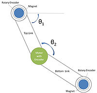
The monkeybot behaves like a double-pendulum system. The geometry, and our definitions of angles is shown to the right. The two angles important to us are the angle between the top link and a horizontal reference, and the angle between the two links. The rotary encoders over the magnet provide a measurement of the first angel, while the motor encoder measures the second.
With these two angles we are able to implement a variety of control laws as described below.
Simulation
We developed a simulation that shows how the brachiating robot would ideally climb given a closed-loop control law that continuously pumps energy into the system. The simulation assumes point mass objects (red dots), viscous friction at the revolute joints, and an input forcing function at the motor joint (middle red dot). The simulation was done in Mathematica 7.0 and the code is hosted as a Google code project.
Control Method
Closed Loop Control
We first attempted to control the DC motor using feedback from a rotary encoder placed directly over each magnet. From this encoder, using both the A and B channels, we are able to determine the sign of the top link's velocity. We then implemented a simple control law in which the motor is full on in the same direction that the top link is rotating (switching only when the sign of the velocity changed). This causes the lower link to pump in phase with the top link, mimicking the motion of a person on a swing set.
With this control law we were able to pump energy into the system, however, we were never able to add enough energy to get the bottom magnet to a height equal to or above the top magnet. Starting from a resting position, with the lower link dangling straight down, the bottom link pumps in phase with the top link. The bottom magnet gradually gets higher and higher, but seems to stop increasing when it reaches a height slightly below the fixed magnet. Friction seems to be the main reason why the robot can not climb.
We also implemented a control law where the lower link pumped out of phase with the top link. This caused a large increase in the movement of the top link, however, the bottom magnet stays in nearly the same position throughout.
Open Loop Control
Our second approach was an open loop, time based algorithm. It involves no feedback and is just a simple set of commands implemented by the PIC. In order for the monkeybot to climb, the first link must be started with some potential energy. The magnets are both on and at the same height when the algorithm begins. The algorithm is as follows, it can be tuned by changing the values A,B,C,D which are on the order of 500-600 milliseconds.
 Release magnet one
 Motor on counterclockwise for A milliseconds
 Motor off
 Magnet one on
 Release magnet two
 Motor on counterclockwise for B milliseconds
 Motor off
 Magnet two on
 Release magnet two
 Motor on clockwise for C milliseconds
 Motor off
 Magnet two on
 Release magnet one
 Motor on clockwise for D milliseconds
 Motor off
 Magnet one on
This process is repeated, and overtime, the monkeybot climbs. A video of this can be found here.
Mechanical Design
Parts List
The robot contains:
           Two acrylic links
           Two rotational ball-bearings
           Two electro-magnets
           Two rotary encoders
           One Pittmann GM8224 DC Motor with 19.5:1 Gear Head
           One large steel surface
Design Considerations
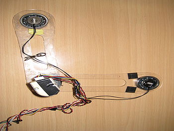
The two links, made of 1/8” thick acrylic, create the body of the robot and create a mount for both bearings and the motor. The thickness and the material was chosen to minimize weight, and thus the torque required to swing the robot. The links were produced using a Laser Cutter. The rotational ball bearings mount on the links and hold the magnets, allowing the robot to swing around a fixed point. The encoders are mounted above the magnets on a bridge, so that they are capable of measuring the rotation of the link around the magnet.
The Pittman motor was chosen to provide enough torque to the links to overcome friction. The gear head is also needed to get the necessary torque. With the gear head, the Pittmann is capable of providing 2.1 Nm of torque, which is more than enough for this application. However, the motor is rather large and thus increases the overall weight of the system.
The data sheet for the Pittamnn motor can be found here.
Electrical Design
Parts List
The robot contains:
           One PIC 18F4250 @ 40 MHz
           Two 74HC00 Quad 2-input NAND
           One L293B four half H-bridges
           Terminal strips (enough for ten connections)
           Two 10-pin headers (for rotary encoders)
           Two TIP31C NPN Power Transistor TO-220
           One LS7083 Quadrature Clock Converter
Design Considerations
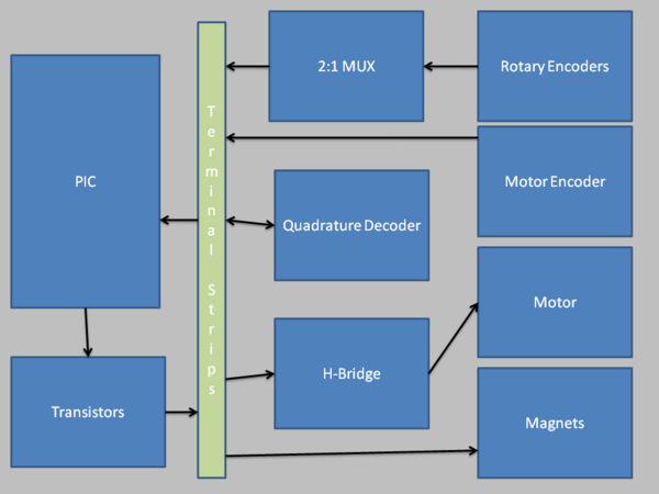
As the central processing unit, the PIC controlled the magnets, motor, and rotary encoders. Below is a block diagram of the circuit. The multiplexer circuit was built with NAND gates and cut down on the redundant circuitry that would have been needed to interface with both rotary encoders individually. The decision to use the terminal strips allowed us to modularize the interface between the PIC and the rest of the circuit. For example, our closed-loop control law could have made use of the angular position of either the fixed pivot or the motor pivot in an attempt to pump energy into the system. The terminal strips allowed us to easily and quickly make the changes without the need to reprogram the PIC in order to test which approach was better.
The circuit design was originally meant for the PIC 18F4331 with its built-in hardware quadrature decoder interface for reading the fixed pivot angular position or velocity. The LS7803 was meant to complement the built-in quadrature decoder by reading in values from the motor encoder allowing us to know the relative position of the robot on the magnetic surface. Instead, the PIC18F4520 was used throughout our project and the LS7803 became a convenient way to detect change of velocity direction useful for our closed-loop controller.
Code
The implemented code is straightforward. The main program sits in a loop waiting for commands from an RS-232 connection. For example, whenever the user hits 'o' a preprogrammed timing sequence (i.e. the open-loop controller) is executed that enables the robot to climb. As seen in the video, we swing counter-clockwise twice and then clockwise twice to avoid the wires from tangling up with each other.
Although commented out, the closed-loop controller can be activated by inserting an empty infinite loop and enabling the commented interrupts. We made use of the Capture/Compare/PWM modules, CCP1 and CCP2, on the PIC. As configured, every 16th rising edge of the LS7803 quadrature up or down pulse for the CCP1 and CCP2 module, respectively, generated an interrupt. It is important to note that, if sampled correctly, an up or down pulse is a mutually exclusive event on the LS7803. Because each pulse represented a +/-1 increment to our position counter, every time an interrupt occurred, we would know the sign of a links velocity by the interrupt that was triggered. We used this information to switch motor direction in our closed-loop controller.
We have attached the code as-is for educational purposes only. Here is the zip file containing the entire PIC-C project files for the code.
Results and Reflections
We successfully created a climbing robot, however, the monkeybot was not as intelligent as we had originally hoped. It was unable to swing itself up from rest using a variety of closed loop control laws, most likely due to the large amounts of friction. To combat the high friction, we started the swinging link with some potential energy. From that point, it was relatively simple to design and tune an open loop time based algorithm which causes the robot to climb.
A closed loop control system using encoders on both the magnets and the motor would improve this project. With this feedback, all of the necessary angles are known and thus the state of the robot is known at all times. If the robot knows its own position, it is better able to adjust to errors, such as a magnet slipping or variations in friction. An open loop time based algorithm can not adjust itself, as the timing of the sequence is hard coded.


