Difference between revisions of "Gears"
From Mech
Jump to navigationJump to search| (10 intermediate revisions by the same user not shown) | |||
| Line 30: | Line 30: | ||
! [[image:spur gears.png|125px|center]] !! [[image:gear-spurgearhead.jpg|125px|center]] |
! [[image:spur gears.png|125px|center]] !! [[image:gear-spurgearhead.jpg|125px|center]] |
||
|} |
|} |
||
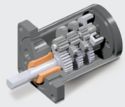
[[Image:globe-gearhead.jpg|thumb|300px|Inside the Globe motor gearhead.|left]] |
|||
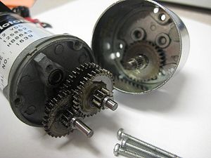
[[Image:globe-gearhead-closeup.jpg|thumb|300px|A closeup of the gearhead, clearly showing 5 stages of spur gear reduction (the gearhead output shaft is disconnected) resulting in a 187.68:1 gear ratio.|right]] |
|||
<br clear=all> |
<br clear=all> |
||
| Line 68: | Line 72: | ||
{| align="left" cellpadding = "25" |
{| align="left" cellpadding = "25" |
||
! [[image:gear-planetarystage.jpg|125px|center]] !! [[image:gear-planetary.jpg|125px|center]] |
! [[image:gear-planetary-anim.gif|center]] !! [[image:gear-planetarystage.jpg|125px|center]] !! [[image:gear-planetary.jpg|125px|center]] |
||
|} |
|} |
||
| Line 89: | Line 93: | ||
|- |
|- |
||
| [[image:gear-harmonicdrive2aligned.jpg|400px|center]] |
| [[image:gear-harmonicdrive2aligned.jpg|400px|center]] |
||
|- |
|||
| [[image:gear-harmonic-drive-anim.gif]] |
|||
|} |
|} |
||
<br clear=all> |
<br clear=all> |
||
| ⚫ | |||
| ⚫ | |||
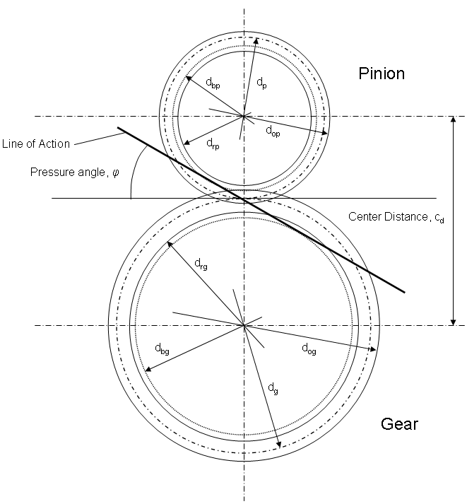
For external spur gears (most common), the gear geometry is as shown in the figure below. The '''''line of action''''' is the line that passes through the intersection of the pitch circles and also tangent to the base circles. |
For external spur gears (most common), the gear geometry is as shown in the figure below. The '''''line of action''''' is the line that passes through the intersection of the pitch circles and also tangent to the base circles. |
||
[[image:gear-spurdetails.jpg|center]] |
|||
[[image:gear circle geometry.png|center]] |
[[image:gear circle geometry.png|center]] |
||
<br clear=all> |
|||
| ⚫ | |||
| ⚫ | |||
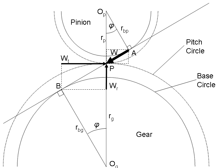
Gear meshing results in contacts with normals along the line of action, so the resultant force, <math>W</math> is along this line. This results in both tangential and radial forces, <math>W_t</math> and <math>W_r</math>, on the gear pair. When these gears are mounted on a shaft, the radial force causes a bending moment while the tangent force causes both a bending moment and a torque. |
Gear meshing results in contacts with normals along the line of action, so the resultant force, <math>W</math> is along this line. This results in both tangential and radial forces, <math>W_t</math> and <math>W_r</math>, on the gear pair. When these gears are mounted on a shaft, the radial force causes a bending moment while the tangent force causes both a bending moment and a torque. |
||
[[image:gear triangles.png|center]] |
[[image:gear triangles.png|center]] |
||
==References== |
==References== |
||
Latest revision as of 07:34, 2 March 2011
Types of Gears
Spur Gears
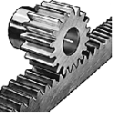
Rack and Pinion
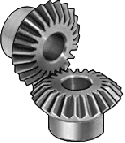
Bevel Gears
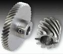
Helical Gears
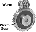
Worm Drives
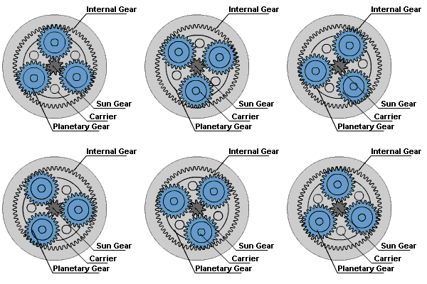
Planetary Gears
Ball Screw/Lead Screw
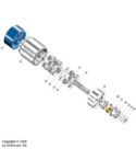
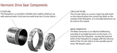
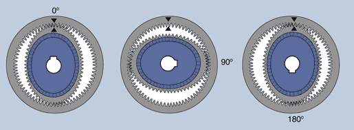
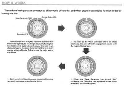
Harmonic Drive Gears
|
Spur Gear Geometry
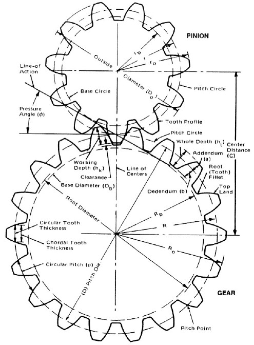
For external spur gears (most common), the gear geometry is as shown in the figure below. The line of action is the line that passes through the intersection of the pitch circles and also tangent to the base circles.
Spur Gear Meshing and Forces
Gear meshing results in contacts with normals along the line of action, so the resultant force, is along this line. This results in both tangential and radial forces, and , on the gear pair. When these gears are mounted on a shaft, the radial force causes a bending moment while the tangent force causes both a bending moment and a torque.
References
- Stock Drive Products/Sterling Instrument, http://www.sdp-si.com
- McMaster-Carr, http://www.mcmaster.com
- Harmonic Drive, LLC, http://www.harmonic-drive.com

