Difference between revisions of "File:SPI circuit.PNG"
From Mech
Jump to navigationJump to search (This is the circuit used for SPI communication between two PIC32s. It uses two digital inputs from push button switches to control what byte of data is sent from the master to the slave.) |
(uploaded a new version of "Image:SPI circuit.PNG": This is the circuit used for SPI communication between two PIC32s. It uses two digital inputs from push button switches to control what byte of data is sent from the master to the slave. Edit: Added t) |
(No difference)
| |
Revision as of 01:38, 10 February 2010
This is the circuit used for SPI communication between two PIC32s. It uses two digital inputs from push button switches to control what byte of data is sent from the master to the slave.
File history
Click on a date/time to view the file as it appeared at that time.
| Date/Time | Thumbnail | Dimensions | User | Comment | |
|---|---|---|---|---|---|
| current | 23:27, 15 February 2010 | 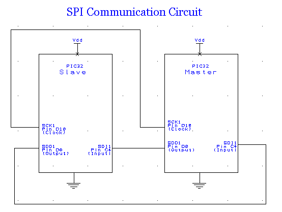 | 554 × 417 (10 KB) | JamesRein (talk | contribs) | Removed the external switches because we changed our code so that it uses the internal switches, USER and PRG instead. |
| 01:38, 10 February 2010 | 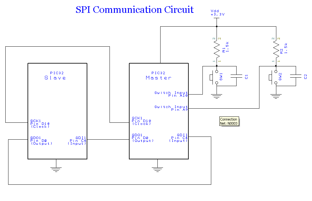 | 997 × 642 (25 KB) | EricWest (talk | contribs) | This is the circuit used for SPI communication between two PIC32s. It uses two digital inputs from push button switches to control what byte of data is sent from the master to the slave. Edit: Added that Vdd = +3.3V, for clarity. | |
| 01:33, 10 February 2010 | 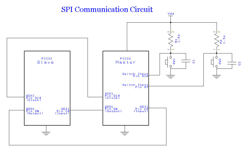 | 1,010 × 638 (25 KB) | EricWest (talk | contribs) | This is the circuit used for SPI communication between two PIC32s. It uses two digital inputs from push button switches to control what byte of data is sent from the master to the slave. |
You cannot overwrite this file.
File usage
The following page uses this file: