Difference between revisions of "Fingertip laser light sensor"
| Line 68: | Line 68: | ||
4) There is a limited range in which the fingertip laser light sensor is accurate. Using the code and setup described above, there was accurate sensing of the fingertip directly in front of the laser and phototransistor to about seven centimeters. |
4) There is a limited range in which the fingertip laser light sensor is accurate. Using the code and setup described above, there was accurate sensing of the fingertip directly in front of the laser and phototransistor to about seven centimeters. |
||
5) The same finger and the fingernail side |
5) The same finger and the fingernail side were used for all of the experiments. Results may be affected by testing with different fingers or whether it is the fingernail side or not, or a side of the finger. Instead of a finger, a white plastic dowel as a control could be used initially for data and then a finger used with more progress. |
||
Revision as of 09:17, 12 February 2009
Original Assignment
I will provide you with a laser that emits a sheet of laser light and a phototransistor for detecting this light. You will investigate their use in developing a fingertip position sensor that senses distance to the finger based on reflected laser light. Your job is to design a sensor circuit and determine the analog voltage readings you get as a function of (1) your finger position and (2) the sensor's location relative to the emitter. You will likely display your results by communicating with a PC or by writing to an LCD (see, e.g., C Example: Serial LCD or C Example: Parallel Interfacing with LCDs).
Overview
A laser that emits a sheet of laser light and phototransistor were the main components of this lab. They are used to investigate a fingertip position sensor that senses the position of the finger based on reflected laser light. The laser is positioned so that it emits a sheet of light just above the plane of the table. If a finger is placed within this field of light, then it will reflect the light back towards the laser. A phototransistor was used to detect the light reflected from the finger. A sensor circuit was designed to take analog voltage readings from the phototransistor with the intention of relating the intensity of reflected light to both the (1) finger position and (2) the phototransistor's location relative to the emitter. The results were displayed by communicating with a PC.
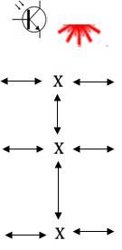
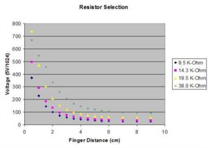
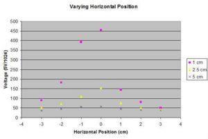
To begin we placed the phototransistor directly adjacent to the laser in order that the distance from the laser to the finger would be approximately the same as the distance from the finger back to the phototransistor. In our first experimental setup, we tested four different resistors in the phototransistor sensing circuit while varying the finger position directly away from the laser (up/down in the figure) in order to get an idea of the level of sensitivity that each resistor would provide. Our second experiment involved moving the finger perpindicular to the laser (left/right in the figure) at three fixed intervals.
Then, we manipulated the position of the phototransistor to see if we could get an improved sensitivity from our sensing circuit. In our third experiment, we put a shield (electrical tape) on the backside of the phototransistor and moved it directly out (down in the figure) into the sheet of light at different positions and varied the finger position in the same (up/down) direction. In the fourth experiment, we moved the transistor directly to the left of the laser in several positions and measured the variation as the finger moved in the up/down direction.
Important Note: The effect of ambient light on the photodiode is significant. In fact, the shadow cast on the photodiode when a finger was placed nearby had a larger effect than the total light reflected from the finger. In order to compensate for this, it was necessary to strobe the laser. The measurement when the laser was on was compared to the measurement when the laser was off to compensate for the ambient light and determine the light intensity contributed by just the laser. (See Code)
Circuit
Code
Data
First Experiment: The phototransistor is placed directly adjacent to the laser. The finger was moved directly away from the laser (up/down in Experimental Setup above). Different resistors were used to investigate sensitivity.
Note: In all experiments voltage was measured on a scale of 0V to 5V and recorded as a 10-bit integer (0-1023).
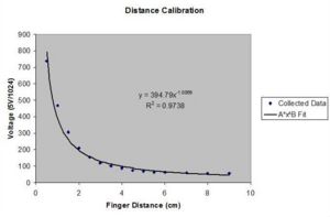
Distance calibration using 19.5 K-Ohm resistor
The fit applied to the curve was of the form:
where I is the intensity of light (measured as a voltage), d is the distance, and A and B are constants.
The best fit to the data was A = 395 and B = -1
The resulting calibration used to calculate distance from the intensity is
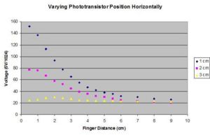
Second Experiment: The phototransistor is placed directly adjacent to the laser. The finger was placed at fixed distances from the laser (1 cm, 2.5 cm, 5 cm) and then moved horizontally (left/right in Experimental Setup above). Using 19.5 K-Ohm resistor.
Note: The negative values are on the same side of the laser as the phototransistor. This results in a shorter distance for the light to travel and a greater intensity on the left side.
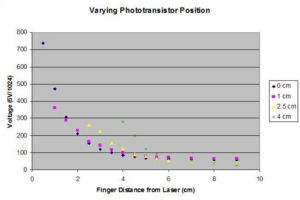
Third Experiment: The phototransistor was moved directly out into the sheet of light (up/down in Experimental Setup). The finger was moved in same up/down direction. Using 19.5 K-Ohm resistor.
Fourth Experiment: The phototransistor was moved to the left of the laser. The finger was moved in the up/down direction. Using 19.5 K-Ohm Resistor.
Limitations and Environmental Factors
There were a few environmental factors that affect the sensors:
1) Ambient light: The overhead light saturated the phototransistor and so the laser was pulsed(the pic was programmed to strobe the laser) in an effort to provide a noticeable difference between the ambient and laser light. As noted above, a finger in front of the transistor cast a shadow which had a larger effect (due to the blocking of the ambient light)than the actual blocking of the laser. Be aware that as the experiment is done any shadow cast on the sensors by a finger or body part will affect the ambient light sensed by the phototransistor and should be taken into account.
2) Lower resistances can be used for the phototransistor to prevent saturation but this also causes a reduced sensitivity to light.
3) The sheet laser provided was not uniform. There were different intensities of light across the line emitted.
4) There is a limited range in which the fingertip laser light sensor is accurate. Using the code and setup described above, there was accurate sensing of the fingertip directly in front of the laser and phototransistor to about seven centimeters.
5) The same finger and the fingernail side were used for all of the experiments. Results may be affected by testing with different fingers or whether it is the fingernail side or not, or a side of the finger. Instead of a finger, a white plastic dowel as a control could be used initially for data and then a finger used with more progress.
