Shielding, Grounding, Noise Suppression, etc.
If your circuit looks like it should work but doesn't, the problem may be caused by electrical noise. In this case, you should make sure that your circuit is properly grounded, isolated, and shielded.
Grounding
Types of Grounds
There are generally three types of grounds: earth ground, signal ground, and chassis ground.
A ground represents a common node, but there are some differences among the types.
The earth ground denotes a physical connection to the earth, which is conventionally defined to be 0 volts. On electrical appliances, this is the third pin on the power plug. However, many circuit diagrams will use this symbol to designate 0V reference even if there is no physical connection with the ground.
The second type, the signal ground, is used as a reference for data transmission lines. The signal ground is generally not connected to the earth to isolate it from electrical noise and interference from electric currents and fields in the earth. Thus, there is often a significant voltage difference between the signal ground and the earth ground.
The third kind is known as the chassis ground, and is usually connected to the conducting shell or chassis of that particular piece of equipment. For example, the negative termial of a car battery is wired to the metallic shell of the car. This provides a reference voltage that may or may not be connected to the earth, although for most high-power appliances, it usually is. Not connecting the chassis ground to the earth ground can result in a voltage difference between the chassis ground and the earth ground, which leaves the risk of electrical current (including static electricity) finding a path between the chassis and earth through something...or someone. This is the reason why fuel trucks must be grounded while dispensing fuel—the voltage difference can result in a spark and explosion.
Grounding Considerations
Because of the resistance of our conductors, it is possible for our ground wire to have difference voltages at different points along the wire when current is flowing through it. To keep wire resistance and voltage differences at a minimum, there are several things we can do:
- Use large ground wires and wide ground traces/planes on PCBs, and physically attach the grounds close to each other.
- The ground wire should also not be connected in a loop with itself; changing magnetic flux through the loop can induce a current in the loop.
Power circuitry often causes electrical noise on the power supply. The power supply may also see voltage spikes from commutator brushes or other circuitry.
- Put a capacitor across power and GND. A large capacitor (10's or 100's of uF) can filter out low frequency changes in the voltage—it acts as a sink that can damp large changes in voltage (remember, the voltage across a capacitor cannot change quickly, but the current can). Capacitors often used for this purpose are polarized tantalum electrolytic capacitors.
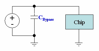
- Use bypass capacitors (for example, a 0.1uF unpolarized ceramic capacitor) across the power and ground of a chip. This capacitor will help "fill in" sudden voltage dips caused by noise. We can use small capacitors at signal inputs and outputs to "clean up" the signal in a similar way.
- Another good thing to do is to isolate our motor/actuator circuit from our logic circuit. We can do this with an opto-isolator which uses an optical emitter/detector pair to send signals back and forth between the separated circuits.
Minimizing Electro-Magnetic Interference (EMI)
A changing magnetic field can induce a current that can interfere with your signal. The voltage induced by the magnetic field depends on the rate of change of the magnetic field and the area your circuit loop encloses:
Some common sources of changing magnetic fields are:
- 60 Hz ambient from AC power
- power transformers
- computer monitors
- machinery (especially motors)
A few ways reduce such interference are:
- move the device away from the source of interference.
- use short lead wires
- use twisted pair leads.
- use shielded cable with the shield attached to the chassis at both ends.

