PIC32MX: XBee Wireless Round-trip Latency
Overview
It is often useful to send signals from one PIC to another wirelessly. One way to achieve this is to use XBee communication. XBee chips use radio frequency waves to send wireless signals. These chips can basically replace other, wired forms of communication like RS232.
There are obvious advantages to using wireless communication, but there are also disadvantages. One disadvantage is that wireless communication is generally slower than wired communication. In this lab, we will record the time it takes for a signal to be sent from one PIC to another and back again.
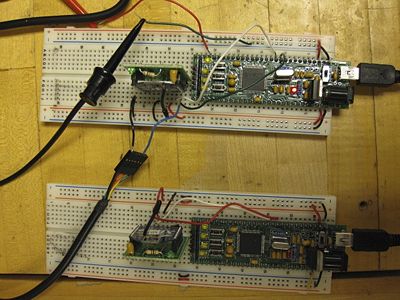
To accomplish this, we have written code for two PICs which control two XBee chips. One PIC-Xbee combination is responsible for sending a signal and recording the time it takes for that signal to come back to it. The second PIC-XBee combination recieves the signal from the first PIC and echos it back. To time the process, the first PIC sets a digital output from low to high just before sending out its signal. When the last character of the signal is recieved back, the PIC sets the output pin low. This low-high-low pulse is observed and timed using an oscilloscope.
Several factors can affect the speed at which the process happens. For one thing, XBee chips are able to communicate using various baud rates (the rate, in bits per second, signals are sent and recieved). Another factor that can affect the speed of wireless communication between two PICs is the size of the message being sent. To see how each of these changed the communication time, we ran two experiments. First, we varied the baud rate of the system while holding the size of the message constant. Then we varied the size of the message while holding the baud rate at a maximum. A third experiment was developed to see if the distance between the two communicating XBee chips would affect the latency time, but no changes were observed within the confines of the Mechatronics lab.
Circuit
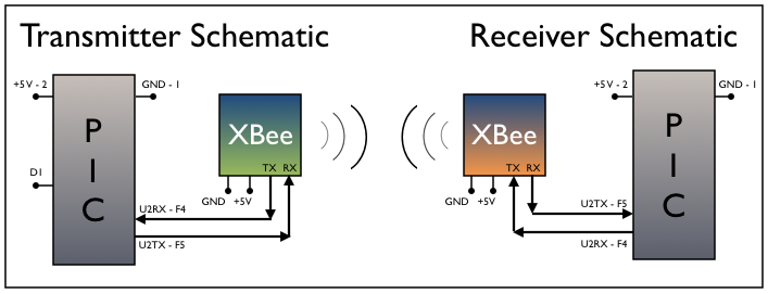
The following diagram depicts the circuit we used for our experiments. The theory behind the circuit is simple. The transmitter PIC TX pin is connected to the XBee RX pin. The XBee broadcasts the signal. The receiver XBee's RX pin is connected to the PIC's TX pin. The receiver PIC's RX pin is then connected to the XBee's TX pin.
The arrows symbolize an elementary view of the signal flow during the timing process and Pin D1 was used for clocking the trip time by setting it high and low.
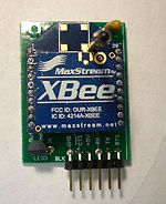
The pinout of the XBee chip can be seen in the image to the right. Note the RTS and CTS pins on the XBees were not used during the experiment. Notice how the XBee chip is constructed so that it can be stuck into a solderless protoboard or plugged directly into a RS232 cable. We were using the standard version of Digi's XBee chip, but they sell a "pro" version which they claim works up to a mile away. The advantage to this is that both the pro and consumer versions of these chips have the same pin-outs and they are interchangeable. That is, the XBee chips are removable from the XBee Interface Board wherein the pro and standard versions can be used.
X-CTU
We conducted the experiments at various BaudRates and this involved reprogramming the XBee chips. This was easy to do, but required the use of special software. Digi's [X-CTU] is hyperterminal-like software which allows for easy interface between a computer and the XBee chips. After downloading and installing it, the chips can be reprogrammed. The steps to reprogram the chips with different BaudRates are as follows:
- Connect the end of the RS232 cable to the XBee chip. (Make sure the black wire connection on the RS232 cable plugs into the GND pin of XBee chip).
- X-CTU should automatically detect the chip. Click on the terminal tab in X-CTU
- Type "+++" (without the quotation marks) and the chip should reply with "OK." This means that you are connected and talking with the chip. After ten seconds of inactivity in this mode, the chip will automatically disconnect itself and you'll have to type "+++" again.
- In order to change the baud rate type the following command: ATBD followed by 0-7 depending on the BaudRate you want
- 0 = 1200 bps
- 1 = 2400 bps
- 2 = 4800 bps
- 3 = 9600 bps
- 4 = 19200 bps
- 5 = 38400 bps
- 6 = 57600 bps
- 7 = 115200 bps
- After typing the command and the number, press enter and they type ATWR to write the command to memory. Type ATCN to exit command mode. The chip should be reprogrammed.
Note that after reprogramming the chip, in order to continue using the terminal to communicate with the chip you will have to change the BaudRate settings in X-CTU. This can operation can be done from the the computer tab. You can select various standard BaudRates from the dropdown menu. If you want to make sure the chip has been correctly reprogrammed, you can change the BaudRate in X-CTU and then try to reconnect with the XBee chip by typing "+++" in the terminal. If you get an "OK" response then the chip has been correctly reprogrammed. For more information on using X-CTU and XBee chips, see XBee radio communication between PICs.
Code
Transmitter Code
The code below is for the transmitter XBee chip. Note that the message string includes only one period, and the period is the last character in the message. The program know it has recieved the whole message back from the reciever when it recieves the period.
/**********************************************************************

     Transmitter Code
     Lab 5: High Speed XBee Latency
     George Randolph
     Nathan Hirsch
     10 February 2010

This code is for the TRANSMITTER XBee chip.  It takes a string of characters and
sends them from the PIC to the XBee, which then broadcasts the message out into the world.  The
reciever chip should receive the message and echo it back to the transmitter.  When the transmitter first broadcasts the message, a pin on the PIC is
set to high.  When the message is successfully echoed back, that pin is set low
so the whole process can be timed using an oscilloscope.

**********************************************************************/


// ****** Includes
#include "HardwareProfile.h"

// ****** Constants
#define DESIRED_BAUDRATE    	    (115200)	      // The desired BaudRate Note: This must be changed when changing the XBee chip's BaudRate
#define PIN_D1			LATDbits.LATD1        // These commands format pins D1-D4 as digital outputs.
#define PIN_D2			LATDbits.LATD2        // Note we used D1, but you may find it necessary to use different output pins.
#define PIN_D3			LATDbits.LATD3        // This code sets up 4 potential digital outputs.
#define PIN_D4			LATDbits.LATD4

// ****** Variables
unsigned int Time;
char RS232_Out_Buffer[64];  			      // The buffer may be changed if lots of data is being sent at a high BaudRate
char message;


// ****** Function Declarations
void initInterruptController();

// ****** Main Function
int main(void)
{
	int	pbClk;
	//initUART2(pbClk);

	// Configure the system performance
	pbClk = SYSTEMConfigPerformance(SYS_FREQ);

       //Initialize the LEDs
	mInitAllLEDs();

		// define setup Configuration 2 for OpenUARTx
		// IrDA encoded UxTX idle state is '0'
		// Enable UxRX pin
		// Enable UxTX pin
		// Interrupt on transfer of every character to TSR
		// Interrupt on every char received
		// Disable 9-bit address detect
		// Rx Buffer Over run status bit clear

	#define config2		UART_TX_PIN_LOW | UART_RX_ENABLE | UART_TX_ENABLE | UART_INT_TX | UART_INT_RX_CHAR | UART_ADR_DETECT_DIS | UART_RX_OVERRUN_CLEAR

 	#define config1 UART_EN | UART_IDLE_CON | UART_RX_TX | UART_DIS_WAKE | UART_DIS_LOOPBACK | UART_DIS_ABAUD | UART_NO_PAR_8BIT | UART_1STOPBIT | UART_IRDA_DIS |
                        UART_DIS_BCLK_CTS_RTS| UART_NORMAL_RX | UART_BRGH_SIXTEEN

	// Open UART2 with config1 and config2
	OpenUART2(config1, config2, pbClk/16/DESIRED_BAUDRATE-1);	// calculate actual BAUD generate value.

	// Configure UART2 RX Interrupt with priority 7
	ConfigIntUART2(UART_INT_PR7 | UART_RX_INT_EN);

	// Must enable glocal interrupts - in this case, we are using multi-vector mode
        INTEnableSystemMultiVectoredInt();

	//Set D1, D2, D3, and D4 as a digital output
	LATD |= 0x001E; TRISD &= 0xFFE1;


	while(1) //let interrupt handle the UART
	{
		if (swUser) // swUser NOT pressed
		{
		// Turn off all the lights to show that the message has not been sent
		mLED_0_Off();
		mLED_1_Off();
		mLED_2_Off();
		mLED_3_Off();
		PIN_D1 = 0;
		}
		else
		{
		// Turn on all the lights to show that the message was sent
		mLED_0_On();
		mLED_1_On();
		mLED_2_On();
		mLED_3_On();
       	        PIN_D1 = 1; 			    // Set the pin high to begin the clocking
		putsUART2("1234.\r\n");     // This is where the message goes.  Note the period at the end of the message
		break; 			    // Code only sends the stuff in UART2 ONE time.
		}

	}
   return 0;
 }


// **** Interrupts

// UART 2 interrupt handler and is set at priority 7
void __ISR(_UART2_VECTOR, ipl7) IntUart2Handler(void)
{
	// Is this an RX interrupt?
	if(mU2RXGetIntFlag())
	{
		// Clear the RX interrupt Flag
	    mU2RXClearIntFlag();

		message = ReadUART2();
		mLED_3_On();

		// Toggle LED to indicate UART activity
		if (message == '.') 			      // Note this is the last character of the message we sent.
		{
		           PIN_D1 = 0;		              // Put the Pin to low to finish the clocking
		     // Toggle some LEDs to show that the message was received correctly.
		     mLED_0_Off();
		     mLED_1_Off();
		}
	}

	// We don't care about TX interrupt
	if ( mU2TXGetIntFlag() )
	{
		mU2TXClearIntFlag();
	}
}
Receiver Code
The code below is for the receiver XBee. It takes the message sent by the transmitter and echoes it back to the transmitter.
/****************************************************
	Receiver Code
	Lab 5: High Speed XBee Latency
	George Randolph
	Nathan Hirsch
	10 February 2010
 This is the RECEIVER code.  It takes the message sent by the transmitter and then echoes it back.
 When the whole message is sent, all the LEDs on the receiver board turn on.  When the receiver
 gets some data, only 2/4 LEDs turn on, signaling that some information was received and sent
 back, just not the correct data.  This is just used for visual feedback for the user.
***************************************************/

//*** Includes
#include "HardwareProfile.h"

//*** Constants
#define DESIRED_BAUDRATE    	(115200)      // The desired BaudRate.  Note this must change if the XBee chip's BaudRate is changed


//*** Main Program
int main(void)
{
	int	pbClk;
	unsigned char data;						// The variable that will assing the things to when it reads the UART

	pbClk = SYSTEMConfigPerformance(SYS_FREQ);

	mInitAllLEDs();

	#define config1 UART_EN | UART_IDLE_CON | UART_RX_TX | UART_DIS_WAKE | UART_DIS_LOOPBACK | UART_DIS_ABAUD | UART_NO_PAR_8BIT | UART_1STOPBIT | UART_IRDA_DIS |
                        UART_DIS_BCLK_CTS_RTS| UART_NORMAL_RX | UART_BRGH_SIXTEEN

	#define config2	UART_TX_PIN_LOW | UART_RX_ENABLE | UART_TX_ENABLE | UART_INT_TX | UART_INT_RX_CHAR | UART_ADR_DETECT_DIS | UART_RX_OVERRUN_

	OpenUART2( config1, config2, pbClk/16/DESIRED_BAUDRATE-1);	// calculate actual BAUD generate value.

	while (1)
	{
		while(!DataRdyUART2());	     // Wait for data in the UARTRx
      	data = (char)ReadUART2();	     // Read data from Rx and assign it to "data"

		while(BusyUART2());	     // Wait till the UART transmitter is free
      	putcUART2(data);		     // Write data into Tx.

		if(data == '.')		     // If the data string matches what we sent, turn the lights on
		{
			mLED_0_On();
			mLED_1_On();
			mLED_2_On();
			mLED_3_On();
		}
		else
		{ // If the received data doesn't match what was actually sent, only turn on two lights to show that some data was received, just not the right kind
			mLED_0_On();
			mLED_1_On();
			mLED_2_Off();
			mLED_3_Off();
		}
   }
}
Notes
The message string that was sent ended in a period and there was only one period in the whole message string. We used this to assure that the entire string was read before assigning the digital pin that clocked the entire transfer process to low.
Results
The table below summarizes our results. We ran two experiments. The first involved varying the baud rate while holding the baud rate constant. We sent a message of 90 bytes consisting of the phrase: "Would you like paper or plastic today, sir? Remember, plastic is bad for the environment." (without the quotation marks). Notice there is only one period in our message and that it is at the end. When the program sees the ASCII value for the period it knows that it has captured the entire message. We performed each test 3 times and averaged our measured time results using an oscilloscope hooked up to Pin D1.
| BaudRate | Latency Time (ms) | Expected Time (ms) | Errors? |
|---|---|---|---|
| 1200 | 2360 | 2400 | No |
| 4800 | 600 | 600 | No |
| 9600 | 308 | 300 | No |
| 19200 | 160 | 150 | No |
| 57600 | 64 | 50 | No |
| 115200 | 40 | 25 | No |
In order to calculate the expected time, we multiplied 90 by 8 to get the number of bits we were sending, divided by the BaudRate to get the time and multiplied that by 4. The reason for the factor of 4 is that we assumed the time would, at a minimum, need to travel from the transmitting PIC to the transmitting XBee and from the receiving XBee to the receiving PIC and then back to the receiving XBee and then back to the transmitting XBee and finally to the transmitting PIC. That's a total of four loops. The schematic outlines the signal flow via arrows. We then multiplied that result by 1000 to get the result in ms.
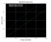
We also conducted an experiment to see the absolute speed messages could be sent varying the byte size. We programmed the XBee chips to broadcast at the highest allowable BaudRate, 115200 bps, and then sent messages of varying lengths. The results can be seen in the table below.
| Message Size (Bytes) | Latency Time (ms) | Expected Time (ms) | Errors? |
|---|---|---|---|
| 5 | 10 | 1.389 | No |
| 10 | 12 | 2.78 | No |
| 15 | 14 | 4.167 | No |
| 20 | 15 | 5.556 | No |
| 25 | 17 | 6.94 | No |
| 30 | 19 | 8.33 | No |
| 35 | 20.8 | 9.772 | No |
| 40 | 23 | 11.11 | No |
| 45 | 24.8 | 12.5 | No |
| 50 | 26.4 | 13.89 | No |
| 100 | 43 | 27.77 | No |
| 142 | 48 | 39.44 | No |
We discovered that at message sizes above about 150 the message would get truncated and not all of it would be echoed back. We reasoned that it had to do with buffer sizes. Throughout all the tests, we kept the buffer in our program at 64. The XBee chip also has an internal buffer. These buffers are similar to the buffer for websites such as youtube.com. If the buffer isn't fast enough, then you have to wait while the video loads. We think that if the buffer size increases, you may be able to send longer message sizes without them getting truncated, however we were unable to perform these experiments due to time constraints.
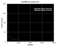
The graph at the right shows the relationship between varying the BaudRate and its effect on the latency time. The expected latency time and our experimentally obtained latency time were very close. It got less and less accurate, however, as the BaudRate increased. This makes sense because the factor of four added to simulated the total "distance" the message had to take played a much more substantial role. At very high BaudRates, the time for the PIC to communicate with the XBee can add to the lag time.
The graph at the right shows the latency time vs byte size. Each test was done twice and the results averaged. The XBee chips were programmed at the highest BaudRates, 115200 bps and the byte size was increased by 5's up to about 50. We observed that at message sizes above about 150, the message would get truncated and not all of it was transmitted. As discussed above, we believe the buffer is the main culprit for this. The main behavior of the graph is mostly linear, which seems to make sense (up to the ~150 byte threshold). Because the XBee chips are operating at their highest allowable BaudRate, the time lag between PIC and XBee communication plays a much bigger role. Again if the buffer were increased, we believe the two lines would get closer to each other. However, considering the timesteps we are dealing with, the expected and measured times are only off by about 10 ms which is still very good.


