NU32: Using the MCP42X1 SPI Digital Potentiometer
THIS PAGE REFERS TO A PRE-RELEASE VERSION OF THE NU32 PIC32 DEVELOPMENT BOARD. FOR INFORMATION, SAMPLE CODE, AND VIDEOS RELATED TO THE PRODUCTION VERSION (2016 AND LATER), AND TO THE CORRESPONDING BOOK "EMBEDDED COMPUTING AND MECHATRONICS WITH THE PIC32 MICROCONTROLLER," VISIT THE NU32 PAGE.
The MCP42X1 is a 7-bit dual digital potentiometer. It is available in total resistance options of 5, 10, 50 and 100 kOhm. It is controlled using SPI communication and a digital output (CS). It has two independent potentiometer channels, each with its own wiper.
Overview
A potentiometer is useful in a variety of circumstances when a variable resistance is needed. A digital potentiometer provides a variable resistor that can be controlled from a microcontroller. Because the MCP42X1 is a 7-bit device, there are 2^7 = 128 possible resistance "steps". By communicating with the IC over SPI, we can choose what step (and thus, resistance) the potentiometer is set at.
The resistance across the PxB and PxW (the wiper) is governed by Failed to parse (MathML with SVG or PNG fallback (recommended for modern browsers and accessibility tools): Invalid response ("Math extension cannot connect to Restbase.") from server "https://wikimedia.org/api/rest_v1/":): {\displaystyle R_{WB} = \frac{5\Omega;}{128} N} where the 5kOhm comes from the total resistance of the pot, depending on the model. The value N is the setting of the pot between 0 and 127.
The pot requires four communication pins from a microcontroller: SPI CLK, SDO, SDI, and one digital output. The pot is powered with 3.3V. This model is a dual pot chip, meaning it has two completely independent potentiometer channels in the same IC, referred to as Pot 0 and Pot 1, respectively.
Details
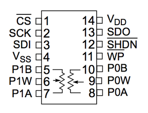
Example schematic when communicating with the NU32, using SPI channel 1:
- Pot 1-CS -----> NU32-F3 (this can be any DIO pin you want, change code accordingly)
- Pot 2-SCK -----> NU32-D10
- Pot 3-SDI -----> NU32-D0
- Pot 4-VSS -----> GND
- Pot 5-P1B -----> P1+
- Pot 6-P1W -----> P1-
- Pot 9-P0W -----> P0-
- Pot 10-P0B -----> P0+
- Pot 12 - SHDN -----> 3.3v (this pin is inverse-shutdown, so we keep it high)
- Pot 13-SDO -----> NU32-C4
- Pot 14-VDD -----> 3.3v
The resistance across PXB and PXW is what changes, labeled above as Px+ and Px-.
Library Functions
Full example project: MCP42X1_Example.zip
MCP42X1.c contains the following functions:
- void SPI_initPots() : sets up SPI channel 1, and CS pin
- void incPot(int pot_num) : will increment wiper by one step
- void decPot(int pot_num) : will decrement wiper by one step
- int setPot(int pot_num, int wiper) : sets the given pot to specific wiper value (0 - 127), returns success boolean
- int readPot(int pot_num) : reads the current wiper setting from the pot, returns (0 - 127)
- void testPots() : runs tests of setting, incrementing, decrementing, and reading both channels to confirm pots are working properly
Sample Code
Initialize and manipulate the pots:
    SPI_initPots();

    //Setting pots to zero...

     setPot(0,0);
     setPot(1,0);
   //both now at 0

    //Setting pots to mid-range (64), or 1/2 the total resistance

     setPot(0,64);
     setPot(1,64);
   // both at 64

    //Incrementing both
    incPot(0);
    incPot(1);
   // (now at 65)

    //Incrementing both
    incPot(0);
    incPot(1);
   //now at 66

    //Decrementing both
    decPot(0);
    decPot(1);
   //now 65


    //Decrementing both
    decPot(0);
    decPot(1);
   //now 64
