NU32: Using the MAX9918 current sensor
THIS PAGE REFERS TO A PRE-RELEASE VERSION OF THE NU32 PIC32 DEVELOPMENT BOARD. FOR INFORMATION, SAMPLE CODE, AND VIDEOS RELATED TO THE PRODUCTION VERSION (2016 AND LATER), AND TO THE CORRESPONDING BOOK "EMBEDDED COMPUTING AND MECHATRONICS WITH THE PIC32 MICROCONTROLLER," VISIT THE NU32 PAGE.
Using the MAX9918 current sensor.
Overview
The MAX9918 is a bi-directional current-sense amplifier.
By placing a small resistance in series with a load, a small voltage is generated across the "current sense" resistor that is proportional to the current through the load. The voltage is small so that most of the supply voltage is still across the load. The MAX9918 amplifies the small voltage, and the output can be read using the ADC in a microcontroller and interpreted as the current through the load.
Details
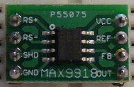
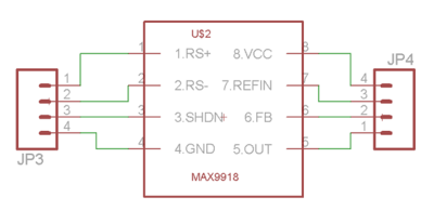
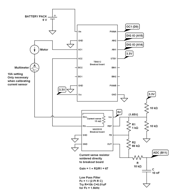
The MAX9918 breakout board brings out all of the pins of the MAX9918 to the breadboard. The chip runs on 5V (on VCC, pin 8) and GND (pin 4). Put the SHD pin (pin 3) high (5V) to have the chip operate.
A 0.015 Ohm current-sense resistor has been soldered between RS+ (pin 1) and RS- (pin 2), rather than giving you a through-hole resistor for your breadboard (the contacts of the breadboard have more resistance than 0.015 Ohm!)
When zero current is going through the current-sense resistor, the output (pin 5) will be the voltage applied to REF (pin 7). Put 1.65V on REF using a voltage divider of 10k resistors between 3.3V and GND.
To set the voltage gain the MAX9918 will apply to the voltage read across the current sense resistor, place a resistance R1 between REF and FB (pin 6) and R2 between FB and output. The voltage gain will be (1 + R2 / R1).
The output voltage is then 1.65 [V] + (I [A] * 0.015 [Ohm] * gain).
Wiring
Calibration
You should calibrate your MAX9918 circuit and note in your code what current the output voltage corresponds to.
Note the output voltage when zero current passes through the current-sense resistor.
Build a circuit that will pass positive current through the current-sense resistor (the RS+ voltage > the RS- voltage). Try to get 2 different values of current through, as large as you can, without burning the resistor you are using to create the current (remember the resistors in your kit are 0.25W). Note the output voltages of the MAX9918.
Do the same for negative currents, and make a plot of the results. Note the slope and use it in your microcontroller code to convert the voltage it reads from the MAX9918 to the current through the load.
More Information
NA


