NU32: Driving RC servo motors
THIS PAGE REFERS TO A PRE-RELEASE VERSION OF THE NU32 PIC32 DEVELOPMENT BOARD. FOR INFORMATION, SAMPLE CODE, AND VIDEOS RELATED TO THE PRODUCTION VERSION (2016 AND LATER), AND TO THE CORRESPONDING BOOK "EMBEDDED COMPUTING AND MECHATRONICS WITH THE PIC32 MICROCONTROLLER," VISIT THE NU32 PAGE.
Driving RC Servo motors with the NU32.
Overview
You can read about RC Servo Theory and a method of creating a drive signal using a 555 timer here.
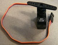
An RC servo has a position controller built in. It will position the output shaft between 0 and 180 degrees if given a pulse of ~0.5ms to ~2.5ms every 20ms (or 50Hz).
An easy way to create the pulse is with PWM. We can set a timer (2 or 3) to 50Hz, and then set the OC module to use that timer, and set the duty cycle to only be in the range that will create pulses of at least 0.5ms and at most 2.5ms. This method is fine if you have a spare timer and OC pin available, but limits you to 5 RC servo motors because there are only 5 OC pins. If your project uses several DC motors and several RC motors, you will run out of PWM pins!
Another way to create the pulses is to do so using a timer interrupt and manually toggling the digital pins. With this method you could control as many RC motors as you want, depending on how you want to set up the code, and with what resolution you need to be able to control the RC servo angle.
Wiring
An RC servo has 3 pins, Power (Red), Ground (Brown), and Signal (Orange). Hook up power to your 6V battery, and ground to your NU32 board. Make sure your battery has common ground with the NU32. Pick an OC pin, like D0, and hook it up to signal. If you are not using the PWM method, and digital IO pin will do.
To physically hook up the RC servo, jam wires into the female connector, they should stay.
Details
Try the PWM method first. Set up timer 2 to 50Hz. There are several options for prescaler: use the prescaler so that you have a large PR value (remember it has to be less than 2^16-1, or 65535). We will see why in a moment.
Now turn on the OC1 module (pin D0) using timer 2, and calculate what duty cycle is required to make a 0.5ms pulse. For example, if we use a 1:256 prescaler for timer 2, and PR2 = 6250 for 50Hz, we have a resolution of (20ms / 6250) = 0.0032ms. For a 0.5ms pulse, we would set OC1RS to 157. For a 2.5ms pulse, we would set it to 781. We would not want to set OC1RS outside of the range 157-781, or the motor might try to move to a position outside of the 0-180 degree range, and break itself trying to get there. Now we have 180/(781-157) = 0.29 degree per count of the OC module, which is fine control of the position of the servo motor. If we use a different prescaler for the timer, we would have better resolution (but do you really need sub-degree resolution, and can the (very inexpensive) RC servo achieve those fine resolutions?
The following code implements this technique: NU32_rcservo_pwm_example.c
More Information
NA
