Disk-on-Disk Rolling Manipulation Project
Overview
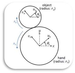
Nonprehensile manipulation primitives such as rolling, sliding, pushing, and throwing are commonly used by humans but are often avoided by robots, who generally use grasping. Dynamic nonprehensile manipulation raises challenges in high-speed sensing and control, as the manipulated object is not in static equilibrium throughout the process which would be the case with standard grasping. An advantage, however, is that dynamics can be exploited to help the robot control object motions that would otherwise be impossible. Our long-term goal is to develop a unified framework for planning and control of dynamic robotic manipulation. A typical manipulation plan consists of a sequence of manipulation primitives chosen from a library of primitives, with each primitive equipped with its own feedback controller. Problems of interest include planning the motion of the manipulator to achieve the desired motion of the object and feedback control to stabilize the desired trajectory. As a first step to understand the nature of dynamic nonprehensile manipulation, we study feedback stabilization of a canonical rolling problem: balancing a disk-shaped object on top of a disk-shaped manipulator (referred to as the hand) in a vertical plane.
Tasks Accomplished
The balancing task of stabilization at the upright position is extended to more difficult problems when having the hand or object
- rotate to a specific orientation, or
- spin at a constant velocity.
We constrain the motion of the circular hand to rotation about its center. We derive control laws that stabilize the object to the balanced position under the kinematic assumption of rolling at all times. The basin of attraction is reduced when the contact is modeled using Coulomb friction, but it is still large with large friction coefficients. This work is successfully implemented using high-speed vision feedback.
The video of this work can be viewed at http://vimeo.com/54405698.
Publication
The initial version of this work which only deals with the balancing problem was presented at the 2012 ICRA.
- J. Ryu, F. Ruggiero, and K. M. Lynch, "Control of nonprehensile rolling manipulation: Balancing a disk on a disk", 2012 IEEE International Conference on Robotics and Automation (ICRA), pp. 3232–3237, 2012.
The completed version of the two advanced tasks is being published in IEEE TRO (online version available).
- J. Ryu, F. Ruggiero, and K. M. Lynch, "Control of nonprehensile rolling manipulation: Balancing a disk on a disk", IEEE Transactions on Robotics, 2013.
Experimental Set-up
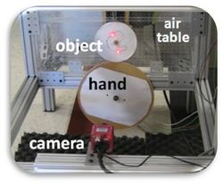
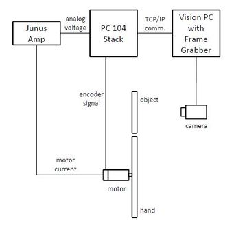
While the detail of the experimental set-up procedure is written in the manual (see Media:DiskOnDisk_Setup.doc), we briefly present it here as follows. The hand is the lower disk, actuated by a harmonic drive DC motor (Harmonic Drive RH-8D 6006) equipped with a 50:1 harmonic drive gearhead and a 500 ppr quadrature encoder giving 100,000 counts per revolution at the output shaft. The commanded current input to the motor is provided through a motor amplifier (Copley Controls Junus 800-1468). The disk-on-disk system is mounted on an air table that provides frictionless support in a plane tilted 79.0 degrees with respect to horizontal (98.2 % of full gravity). Both hand and object are made of 1/4-inch thick acrylic and the object is encircled by a rubber band to increase friction.
The hand control algorithm runs on a PC104 stack with a QNX real-time operating system (RTOS). In addition to the angular position data from the encoder of the hand, the controller utilizes the state of the object disk, which is determined using a high-speed vision system. The vision system, consisting of a PhotonFocus TrackCam camera, a Microenable III frame grabber, and a Windows PC, tracks two markers on the disk at 800 Hz, allowing estimation of the position and orientation of the disk at 800 Hz. The vision program, written in C++, sends the orientation of the disk to the controller PC104 stack via TCP/IP. The tracking markers may be high contrast passive markers (e.g., black on white) or active markers (LEDs in the current implementation).
Amplifier Set-up
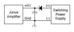
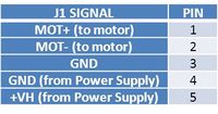
- Connect the output of a DC power supply of 48 V to +HV and GND terminals of the amp using the following diagram. (Junus amp data sheets: http://www.copleycontrols.com/motion/pdf/Junus.pdf)
- Using the USB to RS-232 cable, connect the amp to your PC (Install the driver: Media:Usb-serial-driver.zip)
- Download and install CME2 (Copley Motion Explorer2) from http://www.copleycontrols.com/Motion/Downloads/index.html.
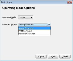
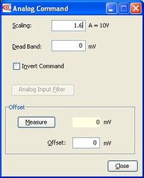
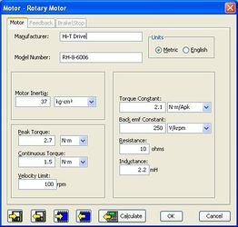
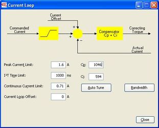
- Set the mode and parameters according to the motor you are using.
- 'Auto Tune' will automatically find the PI controller parameters for your motor.
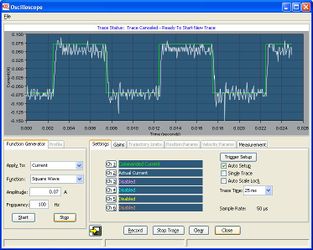
- Check the tracking of the input current by running the menu [Amplifier]-[Scope]
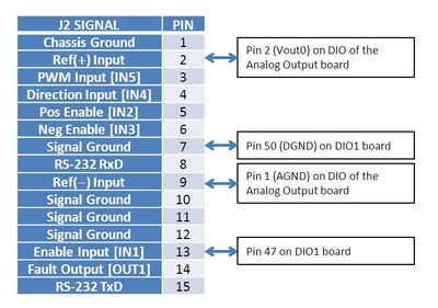
- Complete wiring using the following table.
QNX (PC104) System
- Communication and uploading code
- On the host PC, set a static IP address. For example, with leaving the rest blank, IP address: 192.168.1.10 Subnet mask: 255.255.255.0
- The target PC (QNX machine) also has a static IP. This can be changed in [/etc/system/sysinit] IP address: 192.168.1.65
- On the host, open a command prompt window and enter "telent 192.168.1.65". Both the login and password are "root". (NOTE: if you want to use alias such as "telnet qnx", add a line "192.168.1.65 qnx", spaced by a Tab, in the file [C:\WINDOWS\system32\drivers\etc\hosts].
- On the host, open a second command prompt window and go to the directory containing the code you wish to upload to the QNX machine. "make put" will act the same way as "make" and also send the executable to the target PC using the wput function.
- Your code is now on the QNX machine and ready to execute.
- I/O [IoHardware and individual board drivers]
- The encoder board, MSI-P404-8: 8 encoder channels. Each channel takes in the A and B channels of a single-ended encoder and returns the encoder count using the function GetEncoderCount().
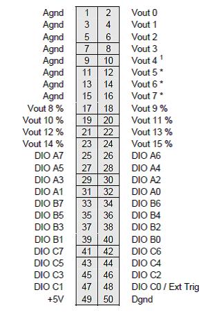
- The analog output board, Ruby-1612-XT (Diamond Systems Corp.): 16 analog outputs (12-bit resolution). To set and output to a single channel, use the function WriteAnalogCh(ch, val). To set a value to be output, use SetAnalogOut(ch, val); to actually output this value, ProcessOutput() must be called. The pinout is in the figure below.
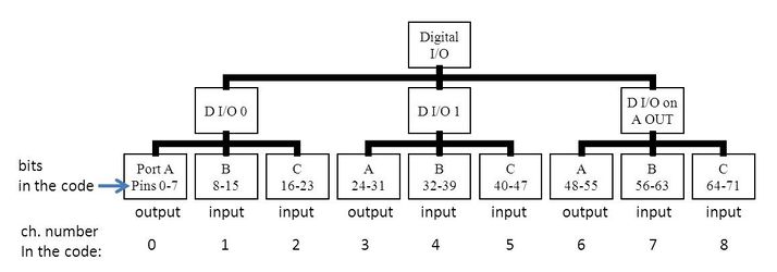
- The digital I/O board, 104-DIO-48E(Acces I/O products, inc.); There are 6 digital I/O ports on the 104-DIO-48E digital I/O board as well as 3 more on the analog output board. The port and pin structure is shown below. ReadDigitalBit(bit) and WriteDigitalBit(bit, state) functions directly read/write bits whereas GetDigitalInBit(bit) and SetDigitalOutBit(bit, state) are effective after calling ProcessInput() and ProcessOutput(), respectively.
- Code: control loop and vision data receiving
- The control algorithm is implemented in [SampleLoopTask::Task() in SampleLoopTask.C]. There is a feedforward model for the motor in [motor.C/h], which calculates the torque (current).
- The camera triggering and communication happens in this loop as well. A trigger pulse is sent to the frame grabber to take a picture. See the related codes in [VisionNet.C/h] that is modified from [MatlabNet.C/h]
- MATLAB communication/data logging [MatlabNet]
- This opens a TCP/IP socket connection with the host PC.
- Every time through the control loop, the output (num[]) is added to the buffer.
- The number of data points to be sent can be changed in the MatlabNet.h file (#define MATLAB_NET_NUM_CH) and must also be changed in the MATLAB code.
- To run the MATLAB code, go to the QnxMatlab folder.
- Run "rtplot.m" and click on the start button.
Running the Program
- After mounting a camera, you must do the calibration. Due to the way the program is coded, you also need to find the center position of the upper disk at the upright position.
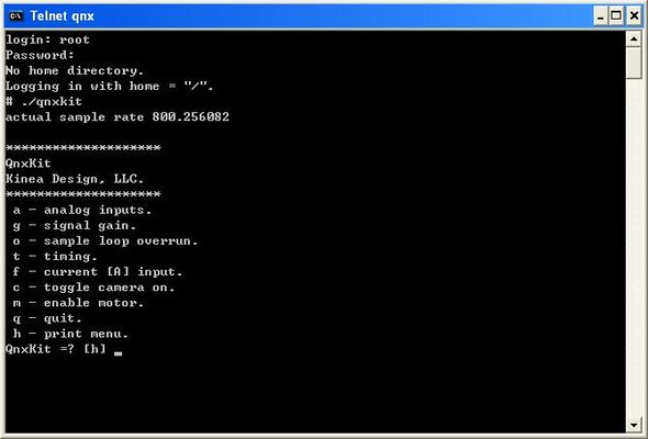
- Run the qnx program by typing ./qnxkit
- Run the vision program [QNX Tracking.sln] on the vision computer. Run F5 on [qnx tracking.cpp].
- Then, click the two dots to track and press 'q'.
- On the qnx interface, type 'c'. Then it starts to calculate the control command (but, no current command is sent to the motor yet).
- By pressing 'm', the motor will now be enabled and start to run the control action.
- If something goes wrong with the motor, press 'q' to quit the program.
Codes
- Media:QnxKit.zip: The codes running on the QNX machine. The control algorithm is implemented in this codes.
- Media:Vision.zip: The codes running on the vision computer. It tracks dots and sends the position data to the QNX machine through TCP/IP.
- Media:QnxMatlab.zip: The codes running on the host computer. Data sent from the QNX machine is collected on the host computer using this Matlab codes.
