Building the blue board
From Mech
Jump to navigationJump to searchBack to Northwestern Design Competition
The blue board stacks with the black board and the green board.
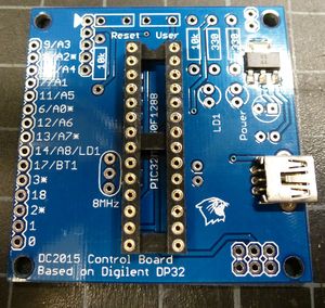
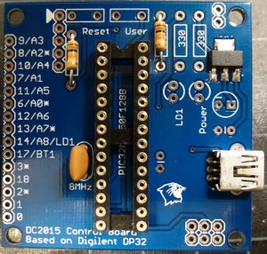
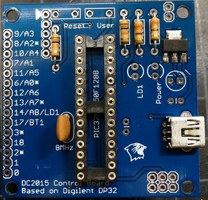
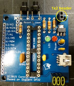
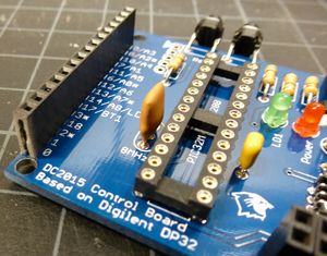
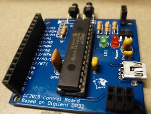
The DC2015 Control board
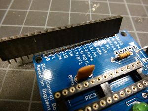
The blue board is a clone of the chipKIT DP32 by Digilent Inc.
It uses the PIC32MX250F128B, running at 40MHz with 128k flash and 32k RAM. The blue board breaks out 15 I/O pins, including 9 analog input and 5 PWM.
The schematic for the board is:
| Pin | Functionality |
| 9/A3 | Digital pin 9, by default analog input 3 |
| 8/A2* | Digital pin 8, by default analog input 2, capable of PWM |
| 10/A4 | Digital pin 10, by default analog input 4 |
| 7/A1 | Digital pin 7, by default analog input 1 |
| 11/A5 | Digital pin 11, by default analog input 5 |
| 6/A0* | Digital pin 6, by default analog input 0, capable of PWM |
| 12/A6 | Digital pin 12, by default analog input 6 |
| 13/A7* | Digital pin 13, by default analog input 7, capable of PWM |
| 14/A8/LD1 | Digital pin 14, by default analog input 8, hardwired to the green LED LD1 |
| 17/BT1 | Digital pin 17, hard wired to the User button BT1 |
| 3* | Digital pin 3, capable of PWM |
| 18 | Digital pin 18 |
| 2* | Digital pin 2, capable of PWM |
| 1 | Digital pin 1 |
| 0 | Digital pin 0 |
Power
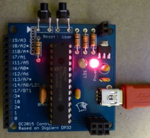
The blue board is powered by a 5V USB source, using a USB A to mini B cable.
The PIC32 is a 3.3V chip - do not put 5V on any of the pins, especially the analog inputs!
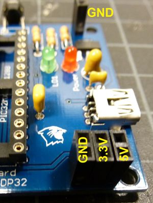
5V, 3.3V, and ground are broken out to be used for sensors and actuators.
Image of power outs
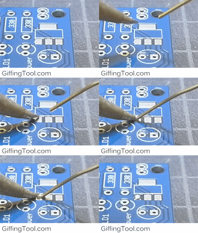
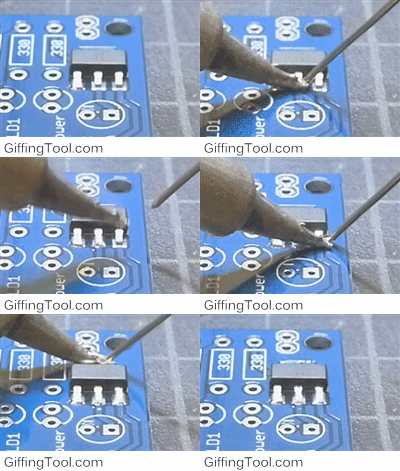
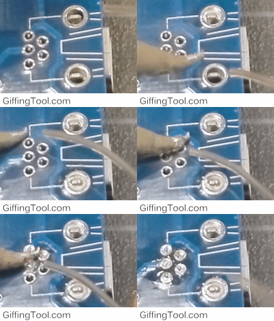
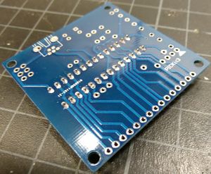
Assembly
Be sure to read up on How to solder
|
|
|
|
|
|
|
|
|
|
|
|
|
|
|
|
|
|
|
|
|
|
|
|
|
|
|
|
|
|
|
|
|
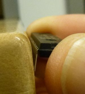
Push the chip in and the board is done! |
|
|
