Adding a magnetic encoder to a GM3 Gearmotor
You may want to add a rotation encoder to your wheel motor. Optical encoders are popular because of the very high resolution (counts per rev) you can obtain.
Here we will add a magnetic encoder, which has advantages of low cost and dirt insensitivity. The resolution is only 1 count per revolution of the motor, but because of the gearing (transmission ratio) it is many counts per revolution of the wheel.
Before doing this exercise, read about how a Rotary Encoder works. In this exercise, you will modify your gearmotor to add an encoder that allows you to keep track of how far your motor has rotated. This encoder is based on the use of magnets and Hall effect sensors instead of a codewheel with lines and optical emitter/detector pairs, but the idea is the same.
Optical Encoder
Instead of making an encoder, as discussed below, you could buy an incremental optical encoder from US Digital for about $20. The E4P encoder has a codewheel that just pushes on to any rotating shaft of the right diameter. Choose your encoder by the size of the shaft, whether it needs to pass all the way through the encoder or not, and the number of counts per revolution you want. You can easily burn out the encoder if you hook it up wrong, so be careful!)
Magnetic Encoder
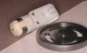
Shown here is the Hobby Engineering Gearmotor-3 with traction wheel, which has a 224:1 transmission ratio
You can also add a magnetic encoder to the Gearmotor-9, which has a 143:1 transmission ratio
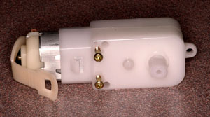
Unclip the motor retention band using pliers
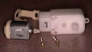
Remove the motor by hand, and the two screws with a small philips screwdriver.
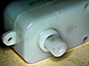
You may have to yank off the semi-round output coupler, which is only lightly glued on anyway.
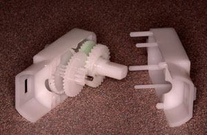
Pry the case apart with a thin blade
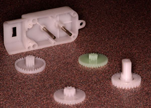
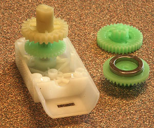
Pull all four gears out
Use 92% alcohol to wipe the grease off the crown gear, the one that turns fastest.
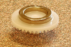
Use superglue to adhere a ring magnet to the back (flat) surface. I found it best to place the magnet, add drops of glue on the outside perimeter, and wick away excess glue with the edge of a paper tissue.
Let it cure. If you are impatient, Blick Art Materials carries Zip Kicker superglue accelerator (and several kinds of superglue.)
This magnet is magnetized such that one semicircle is north and the other south (magnetized left-to-right in the photo)
We have lots of these; they are from Amazing Magnets
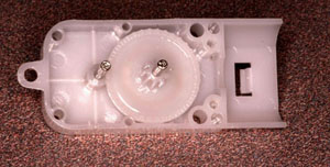
Put it back together. In this photo you can see the magnet ring faintly through the gear
This is the Gearmotor-9, which has slightly different construction than the Gearmotor-3. You only have to take it apart this far.
Unfortunately it has ribs molded into the case where the ring magnet will go. The first gear, when carrying the magnet, still seems to clear the ribs OK, but just barely. One could mill or dremel the ribs down, to be sure
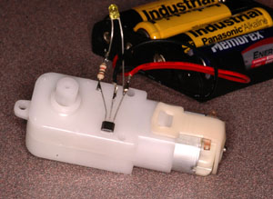
Clean the back surface and superglue a HAL506 hall switch (or similar) to it.
You can find the point of strongest magnetic field on the surface by using a tiny bit of a staple or other steel wire -- it will slide over the surface to the point of strongest field strength.
You can take advantage of this probe to trace out the ring magnet on the surface, as you turn the motor. Find a convenient place to mount the Hall switch.
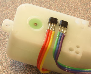
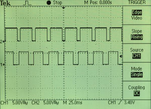
A better way, especially if you want to mount two hall switches in quadrature as I have done here on the Gearmotor-9, is to wire them first and then look at their traces on a scope as the motor is operating. Find the best place to mount them and then glue them in place.
The order of the pins in this photo is 1-2-3:
- pin 1(red, green) = +5V
- pin 2 (orange, blue) = ground
- pin 3 (yellow, purple) = open collector output
Ideally the scope trace will show two square waves, each with 50% duty cycle, and 90 degrees out of phase. I didn't do such a good job here because I guessed the position of the hall sensors. It will work nevertheless.
You may find that if you operate the motor from the same supply as the hall sensors, the motor generates so much electrical noise that the hall sensors will operate erratically. You can solve this with a 0.1uF capacitor across the power supply leads of the hall switch.
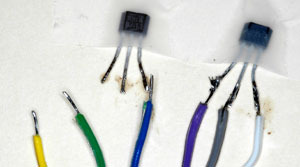
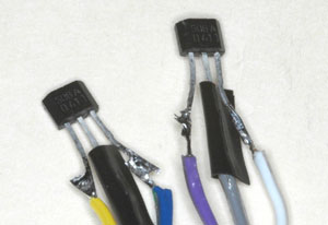
Here's an easier way to attach wires to hall switches. Shorten the leads, splay them out, tape the chips down, and tin the leads. Tin some ribbon cable too.
Solder them together and insulate at least the middle lead. I used tape. Heat shrink tubing is better, if you think of slipping it on in advance.
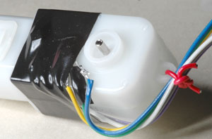
Find the best spots for quadrature signals, mark them with a pen, and then tape the hall switches to those locations with stretchy electrical tape. Tape all the way around. Superglue may not work well enough on this slippery plastic. Some strain relief for the ribbon cable is a good idea; I used the hole at the end.
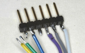
The other end of the ribbon cable can be attached to some 0.1" header for insertion into a solderless breadboard. (If you solder it when it's in there, however, the solderless breadboard will melt.)
Using a hall switch.
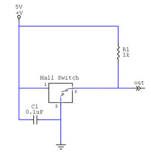
The HAL506 and most hall switches have what is called an open-collector output. That means they can ground their output (for logic 0) but they do not source their output (for logic 1). It is as if there were a switch inside which closes, grounding the output, when a magnetic field is detected. It is the user's responsibility to use a pull-up resistor (R1) to assure that the output voltage is +5 when the switch is open.
Also shown here is the power supply shunt capacitor C1 that will assure reliable operation even if there is noise on the power supply lines.
Decoding A and B signals from an encoder
Now we're going to change those two pulse trains (the A and B channels of the encoder) into one signal that pulses when the encoder rotates clockwise and another signal that pulses when the encoder rotates counterclockwise. The chip that does this for us is the LS7183. Hook up the LS7183 as shown on the datasheet. Choose Rbias according to the maximum frequency of encoder pulses you might ever see (based on the fastest the motor can rotate). Try setting the chip in x1, x2, and x4 counting modes, and look at the two pulse streams coming out of the LS7183. Make sure you understand the 3 different counting modes, and that the pulse streams you see make sense. You can see the pulses on a scope. They are SHORT pulses though, so if you use them to make an LED flash you won't see it.
- You can trigger a 555 timer chip on the low-going short pulses, and set the RC time constant such that the 555's output stays high for 1/100 second. The 555 is capable of supplying large currents. That's plenty of time and current for a nice flash from an LED.
- We could send the two pulse trains from the LS7183 to an up-down binary counter. An up-down conuter has one input that increments the count on a rising or falling edge, and another input that decrements. See the LS7183 datasheet, for examples.
- The LS7184 differs from the LS7183: instead of having pulse outputs for "count up" and "count down", it has one output for "count" and another for "up vs. down.". The latter stays high or low indefinately (until the direction of rotation changes), so that's a signal you can visualize with an LED.
LEDs are dim at 1mA and bright at 20mA. Choose a resistor that will give you the right amount of current through the LED. Keep in mind that the LS7183/4 will only source or sink about 1mA, so you may want some kind of buffer to provide a larger current. Logic chips vary widely in their output current capabilities. Often inverters are used in this buffering role.
