Butterfly Rolling Manipulation
Overview
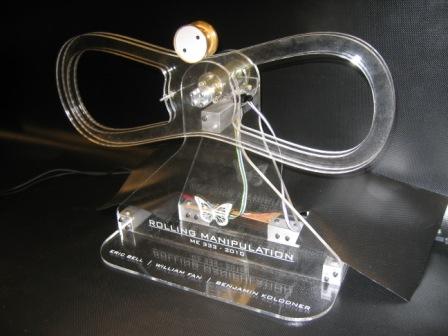
The goal of the rolling manipulation project was to perform a contact juggling move called the "butterfly" on a sphere or circular disk. There are many examples of human jugglers performing the butterfly, including this video of Michael Moschen. The purpose of the mechanical butterfly is to simulate this juggling action for the purposes of nonprehensile manipulation. Prior research on the subject of contact juggling, including a paper by Professor Kevin Lynch, formed the basis for this project. The shape of the apparatus and the general butterfly motion, were obtained from the Lynch paper. Within the scope of four weeks, the circuitry and mechanical systems required to implement this motion were designed and constructed. The following sections will document our step by step process.
Team Members
Eric Bell (Mechanical Engineer, 2010)
William Fan (Mechanical Engineer, 2011)
Ben Kolodner (Mechanical Engineer, 2010)
Mechanical Design
In order to achieve the butterfly motion, a well designed and robust apparatus is needed. The following sections detail the mechanical design of the butterfly apparatus, including the bill of materials and information regarding the choice of butterfly shape.
Bill of Materials
| Item | Number | Supplier |
|---|---|---|
| Socket Head Screw -- 4-40 Thread | 9 | Shop |
| Socket Head Screw -- 6-32 Thread | 20 | Shop |
| Nut -- 6-32 Thread | 8 | Shop |
| Nut -- 4-40 Thread | 6 | Shop |
| Set screw -- 5-40 Thread | 1 | Shop |
| 24 x 24 x .236" Acrylic Sheet | 1 | McMaster #8560K224 |
| 1 x 1 x 11.25" 6061 Al | 1 | Shop |
The Hand: Butterfly Shape
The shape of the actual butterfly was determined in part from the Lynch paper with help from Matlab code developed by Fabio Ruggiero, a PhD student in LIMS. The code manipulates a set of parametric equations to give a two-dimensional shape with continuous curvature. The code can be downloaded here. The user can chose four parameters in order to change the shape of the butterfly. However, it is possible to obtain a shape completely outside the realm of possibility for rolling manipulation with intersections of the spline and extremely sharp corners. The shape used in this project had values around: a0 = 8.6, a1 = -12, a2 = -18, a3 = 36.
After the shape was determined, a set of <x,y,z> points was imported directly into Solidworks and a curve through points (Insert-->Curve-->Through XYZ Points) was created. From there, excess material was removed from the shape to cut down on angular inertia, and holes were created for mounting. Two such butterflies were made on the laser cutter, and the edges were sanded to decrease any imperfections.
The Mount
The mounting system is an incredibly important aspect of the rolling manipulator. It needs to be secure in design, along with allowing easy access to all the parts.
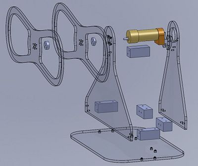
We will start from the base and work our way upwards. The base is made of a large platform of acrylic in order that the manipulator does not shift or tilt during operation. Attached directly to this floor plate are four aluminum blocks with 6-32 socket head screws. The main support structure for the motor and other parts of the device are directly attached to these aluminum blocks via more 6-32 socket head screws. These acrylic plates have enough flexibility that an additional aluminum block was added in the upper region to increase rigidity of the system. From here, the motor is mounted via a simple bolt pattern and extra support in the rear via more 6-32 socket head screws.
The butterfly is secured to the motor via a sandwich of:
- A Butterfly
- Spacer Block with 5-32 Set Screw
- Another Butterfly
- Spacer Block with Relief to Dodge Bolt Pattern of Motor
The parts are held together with long 4-40 socket head screws with nuts on the other end. The through holes on all four parts need to match closely and are clearance for a 4-40 screw to assure assembly.
The Disc
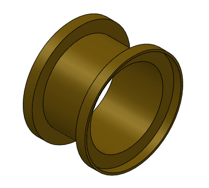
The shape and size of the roller disc is one of the most important parts of the entire design. We decided to create a lightweight, brass rolling disc that would not only hold up to the riggors of testing, but also conduct electricity for future sensing applications of the disc. We made three discs for three with three different weights and wall sizes. In the end, the disc weighs only 22 grams, has 1/32" walls, and has nearly zero electrical resistance.
The solidworks drawing of the disc can be found here
The disc was made via the following steps:
1) Locate at least 1.75" OD free machining brass
2) Rough cut around a 2" length of brass
3) Debur rough edges using belt sander
4) Locate 1 3/4" and 1 11/16" oversized collets
5) Place 1.75" OD brass in Hardinge Toolroom Lathe using oversized collet and closer, with around 1.5" exposed
6) Insert turning tool into compound
6) Machine OD to finish diameter for full length of open area
7) Remove turning tool, insert groover
8) Being careful to reset zeros on the lathe, slowly machine the wide-set groove in the disc
9) Remove grooving tool
10) Center drill, then drill 3/8" through hole
11) Insert boring bar
12) Take successive passes to finish inner diamater as far as possible
13) Remove disc from collet, replace collet with 1 11/16" collet
14) Put Disc in backwards with machined side in collet, remove excess material
15) Use boring bar to finish lip on other side
Note: 1/32" wall can be quite tricky. Take it slow. It takes around 3 hours to make one disc since high precision is needed. If you need advice to make another various disc, please speak to Ben or Steve Jacobson.
Circuit
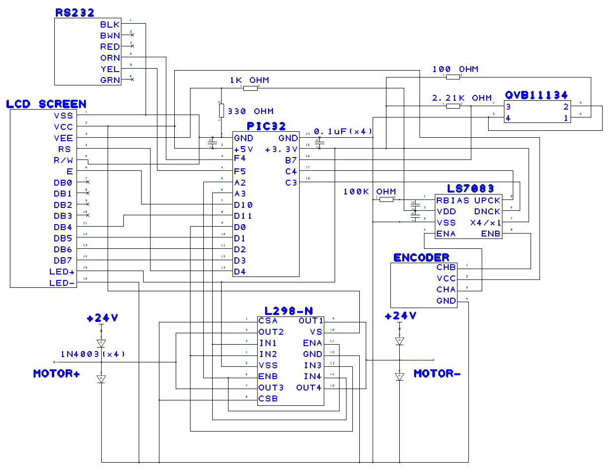
The circuitry involved in this project is fairly simple. The main electrical components include a brushed DC motor with encoder, optical sensor, h-bridge, decoder chip, and LCD screen for debugging purposes.
Parts List
- PIC32 NU32 Board + PIC USB cable
- RS232 cable
- HD44780 LCD
- 100k ohm resistor (1)
- 2.21k ohm resistor (1)
- 1k ohm resistor (1)
- 330 ohm resistor (1)
- 100 ohm resistor (1)
- 0.1uF capacitor (4)
- L298N H-bridge with heat sink
- 1N4003 diodes (4)
- LS7083 decoder chip
- QVB11134 Optical Sensor
- Pittman GM8224 motor
- Breadboard
- Solder board
Circuit Diagram
Motor
A Pittman GM8224 24V motor was chosen for the apparatus. Information for the motor can be found here. Originally, our motor did not use a gear-head in order to reduce backlash. However, this continuously burned out our H-Bridges, so a motor with a 19.5:1 gear-head ratio was selected to provide additional torque.
H-bridge disclaimer
The H-Bridges used in our project burned out at random times, especially if the PIC was turned on and the supply power was also on. This may be due to pins on the PIC initializing incorrectly. Therefore, it is best to start up the PIC, wait a few seconds, then turn on the power supply.
Code
Processing
The purpose of the processing code is to plot the actual movement of the motor against the reference trajectory. The code produces a reference trajectory based on the given equation, a constant time interval, and a k-value and produces 2000 reference points for the motor to follow. Because processing plots one data point per pixel, only every other reference point is saved into an array in the pic. At every reference point, the encoder reads the position and also records this actual position at every other reference point into a separate array. These arrays are fed from the pic into a computer using an RS232 cable when the “read data” button is pushed in the processing GUI. Processing then plots these arrays.
Processing is also used to reset the hand. By pushing the reset button in the processing GUI, processing activates an interrupt which tells the hand to reset using the light sensor and run the main code again.
<insert graph>
Based on the graphs created in processing, the PD control was very effective in controlling the motor. Minor offsets occurred consistently at the beginning and end of each run due to backlash from the motor and inertia of the system mass, but the actual position was very close to the reference trajectory a majority of the time.
Results
As seen by this youtube video, we were able to perform the trick. However, there are a few failure modes, namely:
1) Sliding off the side due to loss of traction. This can be seen here
2) Loosing contact with the surface of the butterfly. This can be seen here.
These might be lowered in frequency with finer tuning of the gains or adjustment of the coefficient of friction on either the disc and/or the acrylic butterfly. The future addition of sensing of the disc location could also help counteract many problems causing failure modes.
Rolling of a disc or ball around a butterfly-like shape has never been done in full gravity. The reliability of the manipulation is around 75% after many hours of tuning. This is very impressive given the time frame of three to four weeks to complete the project.
Next Steps
- Eliminate backlash via gearless motor
- Sense position of the disc using copper tape and resistive wire
- Implement PID control on motor position, along with control of PID using sensing of disc
- Test other butterfly shapes with lower or higher curvature
- Test other disc shapes with different center of masses and weights
- Replace H-Bridges with nicer ones that can take higher amperage
- Optically isolate circuit from noise
