PIC32MX: SPI Communication between PIC32s
Original Assignment
Do not erase this section!
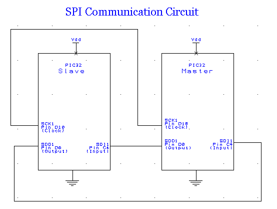
Your assignment is to create code that allows two PIC32 boards to communicate with each other via SPI.
Overview
SPI or Serial Peripheral Interface is a communication method that was once used to connect devices such as printers, cameras, scanners, etc. to a desktop computer. This function has largely been taken over by USB, but SPI can still be a useful communication tool for some applications. SPI runs using a master/slave set-up and can run in full duplex mode, meaning that signals can be transmitted between the master and the slave simultaneously. There is no standard communication protocol for SPI.
SPI is still used to control some peripheral devices and has some advantages over I2CCHANGE THIS TO OUR I2C PAGE!! (another type of serial data communication). SPI can communicate at much higher data rates than I2C. Furthermore, when multiple slaves are present, SPI requires no addressing to differentiate between these slaves. Compared to parallel buses, SPI has the additional benefit of requiring only simple wiring. However, one disadvantage when compared to I2C is that each slave must have a dedicated slave line. A slave line is not necessary when only one slave is present.
Peripheral devices that still use SPI:
• Converters (ADC and DAC)
• Memories (EEPROM and FLASH)
• Real Time Clocks (RTC)
• Sensors (temperature, pressure, etc.)
• Others (signal mixer, potentiometer, LCD controller, UART, CAN controller, USB controller, amplifier)
Basic Operation
SPI requires three lines, and the optional slave select, and is therefore often termed the “four wire” serial bus. These four lines are described in the table below.
| Line | Name | Description |
|---|---|---|
| SCK1 | Serial Clock | Output from master |
| SDO1 | Master Output, Slave Input | Output from master |
| SDI1 | Master Input, Slave Output | Output from slave |
| SS1 | Slave Select | Output from master (active low) |
The master, as its name suggests, controls all communication. By controlling the clock, the master decides when data is sent and received. Within each clock cycle a full duplex communication is carried out; each side sends and receives one bit of information. Because there is no standard communication protocol, the master can either send data or both send and receive data, depending on the needs of the application. Likewise, the slave can either receive data or both receive and send data back to the master.
Using the “Slave Select” line, the master chooses which slave with which to communicate. Note that more than one slave may be selected, simply by applying a logic low to the desired SS lines, as illustrated in the schematic diagram shown above. If a given slave is not selected (its SS is high) it disregards signals sent by the master.
References
SPI Background(www.totalphase.com)
SPI Wikipedia Article (www.wikipedia.org)
More Information (www.mct.net)
Circuit
Code
This code, coupled with the circuit diagram above, sends one of two bytes of data from the master to the slave, and back, so the master can output which byte is sent via RS232 communication protocol.
The data bytes are 0xAA and 0x23. Slave-LED0 toggles when 0xAA is received from the master, and slave-LED1 toggles when anything else (for example, 0x23) is received from the master.
