PIC Servo Controller
From Mech
Theory
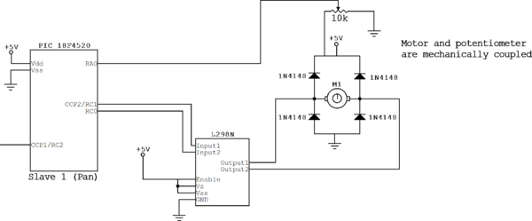
This PIC code and circuit will give you position control over any coupled motor/potentiometer pair. This was tested using a hacked hobby servo but theoretically would give you the same kind of control using any size motor as long as the output shaft was mechanically coupled to the rotation of the feedback pot.
The code and theory borrows from these other pages:
Code
#include <18f4520.h>
#device ADC=10                 // set ADC to 10 bit accuracy
#fuses HS,NOLVP,NOWDT,NOPROTECT
#use delay(clock=40000000)
#use rs232(baud=19200, UART1)  // hardware uart much better; uses  RC6/TX and RC7/RX

#define PanTorqueMax 650       // 650 corresponds to 100% duty cycle for driving the motor full on in one dirction
#define PanTorqueMin -650      // -650 corresponds to 0% duty cylce for driving the motor full on in the other direction
#define pGain 0                // This is the Proportional coefficient, adjust this first
#define iGain 0                // This is the Integral coefficient, adjust this second
#define dGain 0                // This is the Derivative coefficient, adjust this last

signed int32 rise,fall,pulse_width;
int32 msecs=0;
signed int32 PanTarget = 0;
signed int32 PanActual = 0;
signed int32 PanError, PanErrorLastTime=0, PanIntegral, PanDerivative, PanTorque=0;
int16 value;
int i=0;

#int_ccp1                      // This is the CCP capture interrupt, this allows you to use one pin (CCP1) to capture both
                               // the rising edge and falling edge of the servo PWM signal, which leaves the other CCP pin
                               // open for drving the servo motor
void isr()
{
   if (i==0) {output_high(PIN_A1);
              rise = CCP_1;
              setup_ccp1(CCP_CAPTURE_FE);
              i=1;}
   else if (i==1) {output_low(PIN_A1);
                   fall = CCP_1;
                   pulse_width = fall - rise;
                   setup_ccp1(CCP_CAPTURE_RE);
                   i=0;}
}


#INT_TIMER2                    // designates that this is the routine to call when timer2 overflows
void Timer2isr() {
   msecs++;                    // keep track of time

   if ((msecs & 7) == 0) {     // servo routine every 8ms is plenty.  125x/sec
      output_high(PIN_B0);
      PanTarget=pulse_width;
      PanActual=read_adc();
      PanActual=25*PanActual;  // 25 is the coefficient needed to scale up the adc reading to correspond to
                               // standard servo pulse widths (.5 to 2.5 ms)

      PanError = PanTarget - PanActual;      // position error
      PanIntegral += PanError;
      PanDerivative = PanError - PanErrorLastTime;
      PanErrorLastTime = PanError;

      PanTorque = pGain * PanError + iGain * PanIntegral + dGain * PanDerivative;
      TorqueShifted=PanTorque>>16;
      if (PanTorque < PanTorqueMin) PanTorque = PanTorqueMin;
      if (PanTorque > PanTorqueMax) PanTorque = PanTorqueMax;

      if (PanActual<PanTarget){
         output_low(PIN_C0);
         set_pwm2_duty(PanTorque);
      }
      else if (PanActual>PanTarget){
         output_high(PIN_C0);
         set_pwm2_duty(650 + PanTorque);
      }

      output_low(PIN_B0);
   }
}


void main() {

   setup_timer_2(T2_DIV_BY_4, 156, 16);        // clock at 16KHz, interrupt every 4*25nS * 4 * 156 * 16 = 1.0mS
   setup_timer_1(T1_INTERNAL);  //start timer 1

   setup_adc_ports(AN0);               // Enable analog inputs; This will read the ADC on pin AN0
   setup_adc(ADC_CLOCK_INTERNAL);

   setup_ccp2(CCP_PWM);                // PWM output on CCP1/RC2, pin 17
   setup_ccp1(CCP_CAPTURE_RE);

   enable_interrupts(INT_CCP1);
   enable_interrupts(INT_TIMER2);
   enable_interrupts(GLOBAL);

   //set_pwm2_duty(value);             // h-bridge for pan motor from CCP2 (pin 16, RC1) to C0 (pin 16)
   //output_high(PIN_C3);


   while (TRUE) {

      //This is useful for debugging using the RS-232 serial communication

      printf("pulse width: %Lu     Target: %Ld         Actual: %Ld        Torque: %Ld \r\n", pulse_width,PanTarget,PanActual,PanTorque);


   }
}
