Driving a piezo speaker with a PIC
Overview
A Pulse Width Modulation (PWM) output from a PIC microcontroller can be used to play tones on a piezo speaker. With this, musical scales and simple songs can be played on the piezo speaker.
Piezoelectric speakers operate by the converse piezoelectric effect: when a voltage is applied across the terminals, the piezoelectric material in the speaker deflects in one direction. Applying an alternating voltage, such as a square wave, will cause the material to vibrate and create a sound. A constant voltage will not produce a sound.
PWM was used to provide the alternating voltage to drive the speaker (Parallax 900-00001). The period of the PWM determines the tone that will be played; the duty cycle changes the volume.
PWM Period
The frequency range of the speaker was limited by the timer used by the PIC to control PWM, which is Timer 2. First, we determined the PWM frequencies that we could use, which was from about 2kHz to 10kHz. Setting the lowest frequency as our first note (C), a set of timer scaling values that correspond to frequencies that would play the basic notes of an octave of the diatonic scale was found. The period of the PWM is given by the following equation:
Period = 4 * (1/clock speed) * 16 * (scaling value + 1) This is for 1:16 prescaled Timer 2.
Frequency can be calculated by inverting the period. The table below displays the basic musical notes, their timer scaling value and the PWM frequencies in hertz.
| Note | Timer Scaling Value | Frequency (Hz) |
|---|---|---|
| C | 255 | 2441 |
| D | 227 | 2741 |
| E | 204 | 3048 |
| F | 191 | 3255 |
| G | 170 | 3654 |
| A | 153 | 4058 |
| B | 136 | 4562 |
| C2 | 127 | 4882 |
Duty Cycle
To set the duty cycle of the PWM signal you use the following line of code:
set_pwm1_duty(scaling value);
This duty cycle does not refer to the pulse width ratio = but rather the length of time that the pulse is held high . This time is given by:
Duty Cycle = 4 * (1/40MHz) * 16 * (scaling value) for 40MHz clock and 1:16 Timer 2.
Since the pulse width ratio would be at 100% when the duty cycle exceeds the period of PWM, the range of duty cycle values that will produce a sound on the piezo speaker depends on the period of the PWM pulses. Duty cycle values of 1~125 will allow us to play all the notes defined in our code. For very small and very high duty cycles, the volume is low.
Circuit
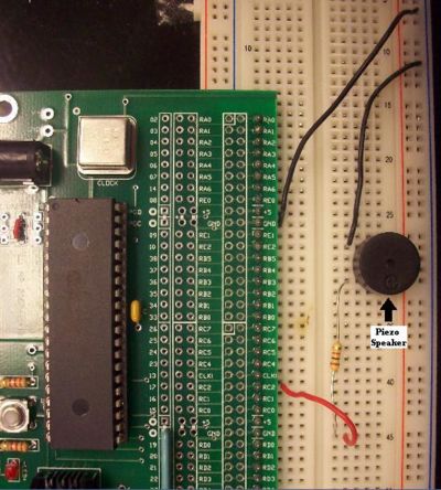
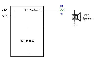
Below is a simple circuit diagram showing the PIC connected to a piezo speaker. The circuit consists of two main components, the PIC 18F4520 and the piezo speaker. The piezo speaker is driven by the PWM output of the PIC (Pin 17, RC2/CCP1). A 1K ohm resistor was added between the PIC and the speaker to limit the current being drawn by the speaker. A potentiometer may be used instead of a fixed resistor, which can act as a volume control. To the right is an example of how to wire the circuit. The piezo speaker is the black circular object.
Code
/*
Code written by Bobby By, Agatha Lee, Dan Niecestro 02-2009
This code uses a PWM signal from PIC 18F4520 to define the frequencies
that produce the basic notes in one octave of the musical scale,
and plays a simple song on a piezo speaker.
The volume of the speaker can be set by changing the duty cycle value (1~125)
*/

#include <18f4520.h>
#fuses HS,NOLVP,NOWDT,NOPROTECT
#use delay(clock=40000000)

//define timer scaling value for each note
#define C 255
#define D 227
#define E 204
#define F 191
#define G 170
#define A 153
#define B 136
#define C2 127
//

#define x 14 //total number of notes in song to be played - modify for specific song

//the song to be played in this demonstration is "Twinkle Twinkle Little Star"
int song[x]={C, C, G, G, A, A, G, F, F, E, E, D, D, C}; //insert notes of song in array
int length[x]={1, 1, 1, 1, 1, 1, 2, 1, 1, 1, 1, 1, 1, 2}; //relative length of each note
int i;

void main() {

      setup_ccp1(CCP_PWM); // PWM output on pin 17, RC2/CCP1
      set_pwm1_duty(30);  // the number changes the volume of the piezo speaker

      for (i=0; i<x; i++) {     //play x notes inside song array

      setup_timer_2(T2_DIV_BY_16, song[i], 16);
                               //set PWM frequency according to entries in song array
      delay_ms(400*length[i]); //each note is played for 400ms*relative length
      setup_timer_2(T2_DIV_BY_16, 1, 16); //the PWM frequency set beyond audible range
                                          //in order to create a short silence between notes
      delay_ms(50);   //the silence is played for 50 ms
      }
}
Bonus Songs
To play these songs, copy and paste the lines into the appropiate location in the code above.
Mary Had a Little Lamb
#define x 26
int song[x] = {B, A, G, A, B, B, B, A, A, A, B, B, B, B, A, G, A, B, B, B, A, A, B, A, G, G};
int length[x] = {1, 1, 1, 1, 1, 1, 2, 1, 1, 2, 1, 1, 2, 1, 1, 1, 1, 1, 1, 2, 1, 1, 1, 1, 2, 2};
Jingle Bells
#define x 25
int song[x] = {E, E, E, E, E, E, E, G, C, D, E, F, F, F, F, F, E, E, E, E, D, D, E, D, G};
int length[x] = {1, 1, 2, 1, 1, 2, 1, 1, 1, 1, 4, 1, 1, 1, 1, 1, 1, 1, 1, 1, 1, 1, 1, 2, 2};


