Difference between revisions of "RGB Swarm Robot Project Documentation"
| Line 8: | Line 8: | ||
'''i.Previous Version''' |
'''i.Previous Version''' |
||
[[Image:E-puck_XBee_board_v1.gif|left|thumb]] |
|||
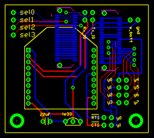
The previous version of XBee interface Extension Board. |
The previous version of XBee interface Extension Board. |
||
Its configuration is shown in the figure on the left. This version of XBee Board does not contain a color sensor in it. Details about this version of XBee Interface Extension Board can be found here: |
Its configuration is shown in the figure on the left. This version of XBee Board does not contain a color sensor in it. Details about this version of XBee Interface Extension Board can be found here: |
||
'''ii.Current Version''' |
|||
[[Image:Epuck_xbee_board_v2.gif|left|thumb]] |
|||
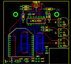
The upgraded version of XBee Interface Extension Board. It is designed by Michael Hwang. This version has a color sensor circuit built in. The details of the color sensor circuit can be found in the color sensor section below. The RTS flow control line on the XBee is connected to the sel3 line of the e-puck. Although the CTS line is not connected to the sel2 pin in this board design, it can be easily connected with a jumper. |
|||
This new version of XBee Interface Extension Board design was actually built and implemented on the e-puck # 3. In order to see if there is any working problem in this board design, it is first tested with the other e-puck which uses the previous XBee Boards. |
|||
The e-puck # 3 upgraded with the new XBee board did not show any problem in communicating with other e-pucks. According to the goal defined, all e-pucks, including e-puck # 3, locate themselves to the desired location. |
|||
Revision as of 12:06, 19 March 2009
Overview
This project consists of two main parts; the improvement of e-puck hardware and the theoretical research on estimating the environment using data collected by the sensor. The e-pucks are improved to have a new version of XBee interface extension board which contains a color sensor to collect data, and have a new LED pattern board at the top of it. By designing this new LED pattern board, each black dot pattern of e-pucks, which has been used by the machine vision system, was replaced by the LED, and the machine vision system is improved in a way to recognize each robot by its LED lights, not by the black dots.
Hardware
XBee Interface Extension Board
i.Previous Version
The previous version of XBee interface Extension Board. Its configuration is shown in the figure on the left. This version of XBee Board does not contain a color sensor in it. Details about this version of XBee Interface Extension Board can be found here:
ii.Current Version
The upgraded version of XBee Interface Extension Board. It is designed by Michael Hwang. This version has a color sensor circuit built in. The details of the color sensor circuit can be found in the color sensor section below. The RTS flow control line on the XBee is connected to the sel3 line of the e-puck. Although the CTS line is not connected to the sel2 pin in this board design, it can be easily connected with a jumper.
This new version of XBee Interface Extension Board design was actually built and implemented on the e-puck # 3. In order to see if there is any working problem in this board design, it is first tested with the other e-puck which uses the previous XBee Boards.
The e-puck # 3 upgraded with the new XBee board did not show any problem in communicating with other e-pucks. According to the goal defined, all e-pucks, including e-puck # 3, locate themselves to the desired location.

