Difference between revisions of "NU32v2: Starting a New Project and Putting it on the NU32v2"
NickMarchuk (talk | contribs) |
|||
| (51 intermediate revisions by 4 users not shown) | |||
| Line 1: | Line 1: | ||
'''THIS PAGE REFERS TO A PRE-RELEASE VERSION OF THE NU32 PIC32 DEVELOPMENT BOARD. FOR INFORMATION, SAMPLE CODE, AND VIDEOS RELATED TO THE PRODUCTION VERSION (2016 AND LATER), AND TO THE CORRESPONDING BOOK "EMBEDDED COMPUTING AND MECHATRONICS WITH THE PIC32 MICROCONTROLLER," VISIT [[NU32|THE NU32 PAGE]].''' |
|||
'''**THIS PAGE IS UNDER CONSTRUCTION AND IS NOT COMPLETE**''' |
|||
'''**NDM 12/27/2010**''' |
|||
Return to [[Microchip PICs#Using the NU32v2|Using the NU32v2]] |
|||
= PIC32 Programming in C = |
= PIC32 Programming in C = |
||
'''Note: Code downloaded from Microchip is constantly evolving, and it is possible that the information below will be outdated for future code releases. This information is accurate for code downloaded from Microchip's website in |
'''Note: Code downloaded from Microchip is constantly evolving, and it is possible that the information below will be outdated for future code releases. This information is accurate for code downloaded from Microchip's website in January 2011. Also, sample code developed by us and others are generally modified from working code for different purposes, and therefore you may find unnecessary legacy code, programming inefficiency, or even incorrect code in some samples.''' |
||
You should complete the instructions in [[NU32v2: Software to Install]] if you have not already. For this page specifically, you need to |
|||
* download and install the MPLAB IDE (Integrated Development Environment) that you use for programming, compiling, debugging, and simulating your PIC code. The MPLAB C Compiler for PIC32 is included in the "complete" installation of the IDE |
|||
* download the NU32v2 Serial Bootloader PC application |
|||
* install drivers for the FTDI USB-to-Serial chip on the NU32v2 board |
|||
The remainder of this page describes how to create a new Project in MPLAB (version 8.xx or X, which is in beta testing), compile a general "Hello World" program to blink the LEDs on the NU32v2, and use the NU32v2 Serial Bootloader PC application to put the program on the NU32v2. |
|||
= Create a New Project in MPLAB 8.xx for the NU32v2 = |
|||
For organizational reasons, it is recommended to have a folder on your computer to store your NU32v2 projects. If you do not already have a space to save your projects, create a new folder and call it PIC_Projects. Each project should have its own folder inside PIC_Projects. |
|||
* Create a folder in PIC_Projects and call it HelloWorld |
|||
* Download the [[Media:procdefs_for_NU32v2.zip | procdefs.ld file from this .zip file]] and place procdefs.ld in the new HelloWorld folder. |
|||
When creating new projects to download to the NU32v2, you must include a linker file. If you have installed a bootloader (such as with the NU32v2), the linker file tells the bootloader to put the program after the bootloader memory to prevent erasing of the bootloader. The required linker file is called procdefs.ld. You will always need to add this procdefs file to your project folders in order to properly install your programs on the PIC. If you do not use this procdefs file, your code will not function properly or at all. |
|||
* Open MPLAB |
|||
* Choose Project -> Project Wizard to create a new project. |
|||
* Click Next. |
|||
* Select the device you are using. The NU32v2 uses the PIC32MX795F512L. |
|||
* Choose the Microchip PIC32 C-Compiler Toolsuite from the drop down menu for Active Toolsuite. This sets up the compiler that will be used for creating the hex code that will be placed on the NU32v2. Click Next. |
|||
* Create a new project called HelloWorld in the folder called HelloWorld (click browse to navigate to that folder). Click Next. |
|||
* Highlight the procdefs.ld file under the HelloWorld folder and click Add. This adds the file to your project. For future projects, if you have existing .c and .h code, this is the step to add these files to your project. For this tutorial, we will be creating our own file, so no additional files need to be added. |
|||
* On this last step, it displays a summary of the previous steps. Click finish. |
|||
You have now created a project. The project window should appear as below. |
|||
[[Image:PIC32_ProjectWindow.jpg|thumb|300 px|left]] |
|||
<br clear=all> |
|||
The procdefs.ld is not the only linker file. |
|||
* In the project window, drag procdefs.ld from the 'Linker Script' folder to the 'Other Files' folder. |
|||
[[Image:PIC32_ProjectWindow2.jpg|thumb|300 px|left]] |
|||
<br clear=all> |
|||
Now we are going to create a .c file to add to this project. |
|||
* Choose File -> New. |
|||
* Choose File -> Save As and call the new file HelloWorld.c in the HelloWorld folder. This will create a source file for your code. You need to include '.c' on the file name, otherwise MPLAB does not know that it is a source file. |
|||
* Right click on the 'Source Files' folder and choose 'Add files'. Choose the HelloWorld.c file to add it to the project. |
|||
[[Image:PIC32_AddFiles1.jpg|thumb|300 px|left]] |
|||
<br clear=all> |
|||
You have now created a project and added a blank source file to your project. You are now ready to code your first program, which will toggle on and off the two LEDs on the NU32v2 board. |
|||
* Cut and paste the code below into your HelloWorld.c file. |
|||
<pre> |
|||
/* HelloWorld.c |
|||
* |
|||
* Our first PIC program, which simply flashes LEDs on the NU32v2 |
|||
* board. We have already installed a "bootloader" on our PIC32, |
|||
* which specifies "configuration bits" that set the clock frequency |
|||
* to 80 MHz (assuming the 8 MHz crystal on the NU32v2 board). |
|||
* |
|||
* |
|||
* HISTORY |
|||
* 1/15/2011 Created by Nick Marchuk, Andrew Long and Kevin Lynch |
|||
* |
|||
*/ |
|||
// plib.h gives access to useful constant and function definitions, found in |
|||
// Program Files/Microchip/MPLAB C32/pic32-libs/include |
|||
#include <plib.h> |
|||
#define SYS_FREQ (80000000L) // clock frequency set by bootloader |
|||
#define LED0 LATGbits.LATG12 // mnemonic constants for LEDs on NU32v2 |
|||
#define LED1 LATGbits.LATG13 |
|||
#define WAIT_LOOPS 2000000 // delay between toggling LEDs |
|||
void initLEDs(void); |
|||
void delay(unsigned int loops); |
|||
int main(void) { |
|||
int i=0; // loop counter |
|||
// SYSTEMConfig() optimizes performance for our clock frequency. |
|||
// in Microchip/MPLAB C32/pic32-libs/include/peripheral/system.h |
|||
SYSTEMConfig(SYS_FREQ, SYS_CFG_ALL); |
|||
initLEDs(); // set LED pins as outputs |
|||
while(1) { // infinite loop |
|||
if(i==0) { |
|||
LED0 = 0; // low output turns an LED on; see NU32v2 circuit |
|||
LED1 = 1; // high output turns an LED off |
|||
delay(WAIT_LOOPS); |
|||
} |
|||
if(i>0) { // toggle the LEDs, wait, and begin loop again |
|||
LED0 = 1; |
|||
LED1 = 0; |
|||
delay(WAIT_LOOPS); |
|||
i = -1; |
|||
} |
|||
i++; |
|||
} |
|||
return 0; |
|||
} // end main |
|||
/* initLEDs() |
|||
* |
|||
* initLEDs sets RG12 and RG13 to outputs to control the LEDs on the NU32v2. |
|||
*/ |
|||
void initLEDs(void) { |
|||
LATG |= 0x3000; // Initializes G12 and G13 to 1 (turns LEDs "off" on NU32v2) |
|||
TRISG &= 0xCFFF; // sets the G12 and G13 pins to outputs |
|||
} |
|||
/* delay(unsigned int loops) |
|||
* |
|||
* This function just wastes time. Note; it just uses an unsigned int number |
|||
* of loops, which should be less than 2^32 - 1, or about 4 billion. If you |
|||
* really want to waste a lot of time, you could use a long long. |
|||
*/ |
|||
void delay(unsigned int loops) { |
|||
int i; |
|||
for (i=0; i<loops; i++) { |
|||
} |
|||
} |
|||
</pre> |
|||
To load this program to the PIC with the bootloader, we need a hex file. MPLAB creates a hex file in the project folder when you compile the program. |
|||
You should complete the exercise [[Getting Started with PIC32]] if you have not already. In that exercise, you |
|||
* Choose Project -> Build all OR F10 on PCs. |
|||
The output window should say 'Build Succeeded'. If it doesn't, fix the errors. |
|||
= Create a New Project in MPLAB X for the NU32v2 = |
|||
* download and install the MPLAB IDE (Integrated Development Environment) that you use for programming, compiling, debugging, and simulating your PIC code |
|||
* download and install the MPLAB C Compiler for PIC32 |
|||
* download the Microchip Applications Library |
|||
* install a "bootloader" on your PIC32 |
|||
* create a "Hello World" program for the NU32 that you compile to a .hex file, download to your PIC32, and run. |
|||
The cross-platform MPLAB X IDE is currently in beta testing, and some features from MPLAB 8.xx are known to be missing or not fully implemented. For example, there is no disassembly view, and the debugger/simulator capabilities are limited. However, it can be used to compile .hex files for loading on the PIC with the bootloader app (process described below). This has been tested on both PCs and Macs for some simple programs without errors, but we cannot be certain there will be no beta-related errors. Use at your own risk. Directions for downloading the software are [[NU32v2: Software to Install|here]]. |
|||
The bootloader is programmed to the PIC's flash memory using a programmer (such as Microchip's ICD). Once the bootloader is there, you should never have to use a programmer again (unless you accidentally overwrite the bootloader in flash memory by using the wrong procdefs.ld "linker" file). From that point on, you should be able to program your PIC simply using a USB cable to connect your PC to the NU32 board. |
|||
Specific instructions below are for MPLAB X running on a Mac. For example, ctrl-click on the Mac replaces right click on the PC. |
|||
After you've installed all the software on your PC, you should have the following directories: |
|||
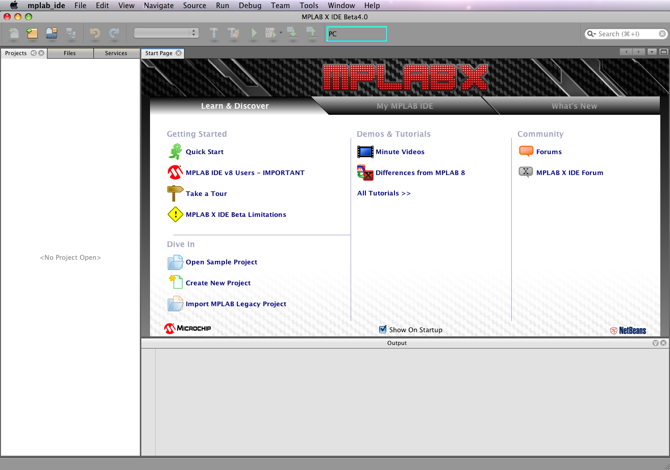
Start up MPLAB X. On a Mac, you should see your screen looks something like [[Media:MPLABX-mac-startscreen.png|this]]. The menus are slightly different from the PC version, to follow Mac conventions. For example, some of the settings under the menu Tools>Options on the PC show up under mplab_ide>Preferences on the Mac. |
|||
* C:\Microchip Solutions: This has a lot of demo code, among other things. The C:\Microchip Solutions\Microchip\Include directory contains .h files that you are likely to need for your programs. Also, C:\Microchip Solutions\USB Device - Bootloaders\HID - Bootloader has .hex bootloaders for different PICs. '''(Note: these .hex bootloaders don't work with the NU32 board, which is why we compiled our own bootloader.)''' It also has PC source software for USB communication with a PIC with the bootloader installed (for programming the PIC without a programmer device). |
|||
* C:\Program Files\Microchip: There is a '''lot''' of stuff under this directory. Two notable directories are MPLAB C32 and MPLAB C32 Suite. These directories look essentially exactly the same, unless I'm missing something. One directory of interest is C:\Program Files\Microchip\MPLAB C32\pic32_libs\include, which has plib.h (function definitions for the peripheral libraries) and subdirectories peripheral (with .h files for peripheral libraries) and proc (with .h files for different PICs containing type definitions and memory addresses specific to the PICs). Another directory of interest is C:\Program Files\Microchip\MPLAB C32\pic32_libs\peripheral, which has directories for each of the peripherals and .c, .inc, and .h source files for the libraries for these peripherals. |
|||
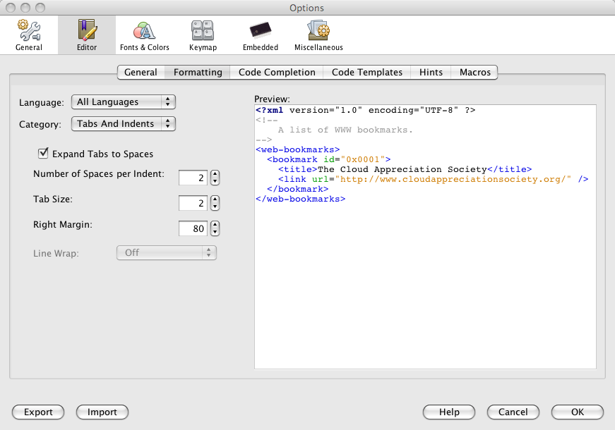
Now try opening mplab_ide>Preferences (or Tools>Options on the PC) and select "Editor" and "Formatting." Choose "All Languages" and Category "Tabs and Indents." Check the box "Expand Tabs to Spaces" and choose 2 for both "Number of Spaces per Indent" and "Tab Size" and a "Right Margin" of 80. Your window should look like [[Media:MPLABX-mac-formatting.png|this]]. Now choose each language individually and uncheck the box "Override Global Options" so each language uses these same formatting conventions. Now click "OK" to apply the changes and close the window. You won't ever need to do this step again. This simply ensures a uniform, non-space-wasting look for the automatic indenting of code you write. |
|||
In addition, you have the HID Bootloader program in your PC's start menu. |
|||
Now, to create a new project: |
|||
When you created your first Hello World project, you went through the following steps: |
|||
* Choose File>New Project. |
|||
** Choose Categories: Microchip Embedded, Projects: C/ASM Standalone Project, and click Next. |
|||
** Choose Family: PIC32, Device: PIC32MX795F512L, and click Next. |
|||
** Choose Hardware Tools: PICkit3 and click Next. |
|||
** Choose Compiler Toolchains: C32 (and you may select a specific version number) and click Next. |
|||
** Use the suggested Project Location (the folder where all your PIC code will be stored), or browse to a new folder. Every project will be a folder in this folder. Type in the name of the project under Project Name. As you type, the name of the folder that will be created will automatically appear. Call the project "HelloWorld," for example. Click Finish. |
|||
* Copy the file [[Media:procdefs_for_NU32v2.zip | procdefs.ld file from this .zip file]] to your new project folder (e.g., MPLABXProjects/HelloWorld.X), where currently there is only a Makefile and an nbproject folder. |
|||
* ctrl-click on the icon "Important Files" in your IDE window and choose "Add Item to Important Files." In the window that appears, navigate to your project directory and select procdefs.ld. |
|||
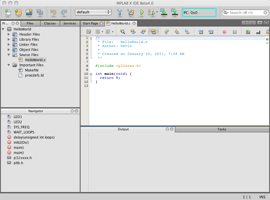
* Now ctrl-click on the icon "Source Files" and choose New>mainp32.c. You will be prompted for the name of the file; let's call it HelloWorld. The extension .c will be appended. Click Finish. You should now have a sample main program populated in your editing window, and your IDE window will look like [[Media:MPLABX-mac-editing.png|this]]. |
|||
** You can add .h header files to your project in the same way to the folder "Header Files." |
|||
** Another option for adding a source file to your project is to copy the file to your project folder in your operating system, then ctrl-click the icon in the IDE and select "Add Existing Item..." |
|||
** While you can add files to your project that are not in the project folder, it is a good idea to keep your files in the folder, at least the procdefs.ld. |
|||
* Now you can replace the sample code by typing in your own program, or cutting and pasting the HelloWorld source code above. Make sure to save your code (File>Save). |
|||
* Now we will create a hex file which can be loaded on the PIC. Click the hammer icon (Build) or hammer plus broom icon (Clean and Build, which erases previous builds and then builds again). |
|||
You should see BUILD SUCCESSFUL at the bottom of your Output window, as shown [[Media:MPLABX-mac-successful.png|here]]. If you look at your HelloWorld folder on your operating system, you will see a new "dist" folder (distribution) which, has subfolders default>production, where HelloWorld.X.production.hex now resides. This is the .hex file you will load on to your PIC. |
|||
# Created a new directory to hold the project, and put the files "HardwareProfile.h" and "HardwareProfile_NU32.h" "header" files into the directory. |
|||
# Used the Project Wizard to create a new project in that directory and specified that you would be using the PIC32MX460F512L microcontroller. |
|||
# Added the HardwareProfile.h and HardwareProfile_NU32.h to your project. (This allows your project to know it has to recompile if these files are changed.) |
|||
# Added procdefs.ld (a "linker" file) to your project. This file is '''different''' from the procdefs.ld file used for your bootloader. These files tell MPLAB where the code should be placed in program memory, and the two procdefs.ld are different so your Hello World program does not overwrite the bootloader code. (This is not the only linker file used, so we put it under "Other Files.") |
|||
# Added two search paths to "Include Search Path," (1) C:\Microchip Solutions\Microchip\Include and (2) the directory of your project, where you are creating your source code. |
|||
# Created a constant "PIC32_NU32" in the MPLAB PIC32 C Compiler tab. |
|||
# Wrote the main.c code for Hello World, added it to the project, and used Project->Build all to create a .hex file that you then loaded on to the PIC32 using the HID bootloader. |
|||
= Using the Serial Bootloader for NU32v2 PC Application = |
|||
So what was the purpose of each of these steps? '''Steps 2 and 6''' defined constants that tell the compiler the microcontroller you are using and the board it is being used on. How are these constants used? Open up HardwareProfile.h, which you included in your project ('''step 3'''). Because you have defined __32MX460F512L__ ('''step 2'''), and because you have defined PIC32_NU32 ('''step 6'''), this file includes "HardwareProfile_NU32.h". Now take a look at the file HardwareProfile_NU32.h. The first thing it does is include "Compiler.h". We can find Compiler.h in C:\Microchip Solutions\Microchip\Include, which we included in our "Include Search Path" ('''step 5''') so the compiler would know where to find it. Let's come back to Compiler.h shortly. |
|||
Now that you have compiled your code, you can use the bootloader to put it on your NU32v2. |
|||
OK, continuing through HardwareProfile_NU32.h, we see that our PIC will have a system frequency of 80 MHz. '''Note that this does not actually set what the PIC does with the oscillator we have provided.''' |
|||
Plug your NU32v2 into a power supply and turn on the board. Plug in the USB cable to the board and your computer. If this is the first time you have plugged the board into your computer, drivers will be installed assigning your board a communication (COM) port number. Note what the port number is. If you are running Windows inside of OSX, you may need to specify that Windows is using the USB port, not OSX. Follow the instructions for your virtual machine to assign use of the USB port. |
|||
Continuing with HardwareProfile_NU32.h, we see that a function "mInitAllLEDs()" is defined. It does two things: it sets the latch bits (LATE) and the "tri-state" bits (TRISE) of port E. LATE and TRISE are the values of Special Function Registers (SFRs) for the digital I/O peripherals and are defined elsewhere, as we will see soon. (See also [[PIC32MX: Digital Inputs]] and [[PIC32MX: Digital Outputs]] for more on using the digital I/O peripherals.) The command "LATE |= 0x000F" bitwise logically "ORs" the current bits of LATE with the bits of the hexadecimal value 0x000F. (This is equivalent to the command "LATE = LATE | 0x000F", and C programmers will notice that this syntax is similar to the syntax a += 3, which is equivalent to a = a + 3.) Note that 0x000F corresponds to a binary value of 0000 0000 0000 1111. So whatever the current values of LATE are, the last four bits (least significant bits) will be 1 after this operation. (Note that 0x000F has only 16 bits, but LATE is technically 32-bit. The first 16-bits are not used, however; see Section 12 of the [[Media:61132B_PIC32ReferenceManual.pdf|PIC32 Reference Manual]]). The command "TRISE &= 0xFFF0" sets whether the pins in port E will be inputs or outputs by doing a bitwise AND with 1111 1111 1111 0000. In other words, the first 12 bits will be unchanged, while the last four bits will be set to outputs (0 = output, 1 = input). These last four bits are going to be used to power our NU32 board LEDs, so they must be outputs. We then see the mnemonic names "mLED_x" given to the (output) values of these four bits. A number of functions are then defined to get the current values of the LEDs and to turn the LEDs on, turn them off, or toggle them. (Note that an output value of 0, or 0 voltage, corresponds to the LED being on; consult the NU32 schematic to see why this is the case.) Finally, functions are defined that will configure bits 4 and 5 of port E as inputs. These are used for the USER and PRG switches on the NU32 board. The constants swProgram and swUser return the current values of these inputs, 0 for low (ground), 1 for high (3.3V). |
|||
Now open NU32v2_Serial_Bootloader.exe. Note that the text in the 'Status' box are red and your COM port is listed in 'Serial Ports'. If multiple ports are listed and you don't know which is your NU32v2 board, you can check 'Ports (COM & LPT)' in 'Device Manager'. Right click on each Port. The NU32v2 uses a chip made by FTDI, so your NU32v2 COM port will say "Manufacturer: FTDI". Usually your NU32v2 has the largest COM port number. |
|||
OK, now let's open Compiler.h from a few paragraphs earlier. We find that since we are using the C32 compiler, it includes the header files p32xxxx.h and plib.h. We will take a look at those shortly, but let's continue with Compiler.h. It also includes some standard C libraries, like stdio.h (libraries for input and output), stdlib.h, and string.h (for string manipulation). It makes a few more definitions which are beyond our scope for now. You might be interested to see the defined function "Nop()" which stands for "no operation," i.e., just waste a cycle. It is defined using an assembly code command using asm("nop"). In other words, if you were coding in assembly (and thank goodness you're not), you would type "nop." You can write low-level assembly code in C using the command asm(). If you are interested, you can always see the assembly code generated by your C code by using View->Disassembly Listing in the MPLAB IDE. |
|||
[[Image:nu32v2_serial_bootloader_open.png|thumb|300 px|left|Initial NU32v2_serial_bootloader.exe window]] |
|||
Let's go back and look at p32xxxx.h and plib.h, referenced by Compiler.h. They can be found under C:\Program Files\Microchip\MPLAB C32\pic32_libs\include. plib.h simply includes a bunch of .h files for the peripheral libraries: 10-bit ADC (adc10.h) which further makes use of definitions in ports.h; I2C serial communication (i2c.h); etc. All of these .h files are under C:\Program Files\Microchip\MPLAB C32\pic32_libs\include\peripheral. We can open one of these many .h files, and we'll see that they define functions that are designed to simplify our use of the peripheral. You can learn more about the use of these peripheral libraries in the [[Media:32-bit-Peripheral-Library-Guide.pdf|peripheral library guide]] (see also Further Reading at the end of this page). Also, you can see the source code for the peripherals to see how the higher-level peripheral functions are created from low-level functions by looking in C:\Program Files\Microchip\MPLAB C32\pic32_libs\peripheral. |
|||
<br clear=all> |
|||
Click "Select .hex File", navigate to your project and select your hex file (projectname.hex). The path to your file will be listed in the first line in 'Status' in green. |
|||
If we now open p32xxxx.h, we find that it simply includes the file p32mx460f512l.h, which is under C:\Program Files\Microchip\MPLAB C32\pic32_libs\include\proc. If we open up this file... whoa! Finally we see where a lot of the data types and variables and constants are defined that have been used earlier. The details are well beyond our scope here, but we can look at the beginning of the file, where the variable WDTCON (WatchDog Timer CONfiguration) is defined as an unsigned integer (a 32-bit integer from 0 to 2^31-1). Also, the data type __WDTCONbits_t is defined, consisting of a set of structures, and then the variable WDTCONbits is defined of type __WDTCONbits_t. The rest of this very large file defines data types and variables for configuration bits, various constants, quantities associated with interrupts, addresses for peripherals specific to the particular PIC, etc. |
|||
[[Image:nu32v2_serial_bootloader_hex.png|thumb|300 px|left|.hex file selected, noted in green in 'Status']] |
|||
OK, we've spent a lot of time tracing #include files to see where various things are defined, configuration bits set, etc. We could spend more time on this, but you get the idea. In the MPLAB IDE, you can click on Configure->Configuration Bits to set some of the Configuration Bits using the IDE, rather than in your source files. I think it is best to have it written in your source files so another programmer knows where to find them. So leave the checkbox "Configuration Bits set in code" checked. |
|||
<br clear=all> |
|||
Next click on the button corresponding to your COM port. The COM port you selected will be listed in the second line in 'Status' in green. |
|||
One more thing that we have not yet mentioned: when you put the bootloader on your PIC, it configured some of the Special Function Registers (SFRs) of your PIC. In particular, open main.c of your bootloader project, and you will see a series of #pragma directives that get executed upon recognizing that you have defined the constant PIC32_NU32. (#pragma directives are compiler-specific instructions, in this case for PIC microcotnrollers, not general C language instructions.) Notice, for example, that FPLLMUL is set to MUL_20 ('''where is this defined?'''), meaning that the PLL (phase-locked loop) in the PIC multiplies the external crystal frequency by 20 (8 MHz x 20 = 160 MHz), and then FPLLIDIV (PLL input divider) divides the frequency by 2, and FPLLODIV (PLL output divider) divides by 1, giving our final system clock of 80 MHz. This is where the actual hardware is configured to give us our actual clock frequency. The peripheral clock is set to the same frequency. USB communication requires a precise 48 MHz clock, and the USB PLL multiplies its input frequency by 12. Therefore, we must provide the USB PLL with a 4 MHz signal, and therefore the bootloader sets UPLLIDIV (USB PLL Input Divider) to 2, to divide the 8 MHz clock by 2. Much of the rest of main.c is devoted to code that allows you to program the PIC by USB communication. |
|||
[[Image:nu32v2_serial_bootloader_com.png|thumb|300 px|left|COM port selected, noted in green in 'Status']] |
|||
OK, going back to the main.c file you created for your Hello World project. After all the includes, a constant SYS_FREQ is defined to be 80 million. '''(NOTE: You could accidentally type 8 million or 800 million, and nothing would work properly! Make sure you type 80 million. Ideally, this SYS_FREQ would be derived from the definitions in the bootloader's main.c file, so you wouldn't have to type again.)''' Then SYSTEMConfigPerformance(SYS_FREQ) is called. This function is defined in C:\Program Files\Microchip\MPLAB C32\pic32_libs\include\peripheral, and one of its purposes is to define some timing constants to hopefully optimize the performance of your PIC (e.g., the use of the pre-fetch cache). Then the LED functions defined in HardwareProfile_NU32.h are used to initialize the LEDs and turn them on or off according to whether the USER button is pushed. |
|||
<br clear=all> |
|||
Next put your NU32v2 board into bootloader mode by pressing and holding the reset button on the NU32v2, pressing and holding the button in the top left breadboard between pin G6 and GND, releasing reset, then releasing G6. The 'Message' box will show "Bootloader v1.1" and the third line in 'Status' will state that your NU32v2 has connected in green. |
|||
Finally, what happens when you "Build All" ('''step 7''')? The compiler compiles any of the individual source files that have been modified since the last Build into .o files, called object code. The linker then puts everything together using a default linker file as well as your procdefs.ld ('''step 4''') and assigns the code to specific addresses in program memory. |
|||
[[Image:nu32v2_serial_bootloader_connect.png|thumb|300 px|left|NU32v2 ready to be programmed]] |
|||
So, to summarize, this was the chain of #include files: |
|||
<br clear=all> |
|||
* The Hello World main.c program included HardwareProfile.h. |
|||
** HardwareProfile.h does little but include HardwareProfile_NU32.h and Compiler.h. |
|||
*** HardwareProfile_NU32.h defines initialization functions to set 4 pins of Port E as digital outputs and 2 as digital inputs; defines convenient names for these pins; and defines functions for turning the NU32 LEDs on and off. |
|||
*** Compiler.h provides a few definitions and includes some standard C libraries (stdio.h, stdlib.h, string.h) as well as p32xxxx.h and plib.h. |
|||
**** plib.h includes the peripheral libraries (e.g., adc10.h, i2c.h, etc.), which you can learn more about in [[Media:32-bit-Peripheral-Library-Guide.pdf|this peripheral library guide]] (314 page pdf). |
|||
**** p32xxxx.h includes p32mx460f512l.h. |
|||
***** p32mx460f512l.h is a big file and makes many of the microcontroller-specific definitions. This includes defining data types and variable names for the peripheral SFRs (e.g., LATE, PORTE, and TRISE, as mentioned above) and some convenient names for addresses and interrupt numbers and vectors. It also includes ppic32mx.h., which defines some other mnemonic variable names. |
|||
Next click the "Program" button. Doing this will clear the memory of your NU32v2, write your code to the board, reset the board and close NU32v2_serial_bootloader.exe. Your code is now running on the NU32v2. |
|||
Finally, the bootloader main.c file defined some of the configuration bits for the clock circuitry, to set the SYSCLK and PBCLK to 80 MHz, and the USBCLK to 48 MHz, given that we have an 8 MHz crystal. |
|||
Latest revision as of 06:23, 16 January 2016
THIS PAGE REFERS TO A PRE-RELEASE VERSION OF THE NU32 PIC32 DEVELOPMENT BOARD. FOR INFORMATION, SAMPLE CODE, AND VIDEOS RELATED TO THE PRODUCTION VERSION (2016 AND LATER), AND TO THE CORRESPONDING BOOK "EMBEDDED COMPUTING AND MECHATRONICS WITH THE PIC32 MICROCONTROLLER," VISIT THE NU32 PAGE.
Return to Using the NU32v2
PIC32 Programming in C
Note: Code downloaded from Microchip is constantly evolving, and it is possible that the information below will be outdated for future code releases. This information is accurate for code downloaded from Microchip's website in January 2011. Also, sample code developed by us and others are generally modified from working code for different purposes, and therefore you may find unnecessary legacy code, programming inefficiency, or even incorrect code in some samples.
You should complete the instructions in NU32v2: Software to Install if you have not already. For this page specifically, you need to
- download and install the MPLAB IDE (Integrated Development Environment) that you use for programming, compiling, debugging, and simulating your PIC code. The MPLAB C Compiler for PIC32 is included in the "complete" installation of the IDE
- download the NU32v2 Serial Bootloader PC application
- install drivers for the FTDI USB-to-Serial chip on the NU32v2 board
The remainder of this page describes how to create a new Project in MPLAB (version 8.xx or X, which is in beta testing), compile a general "Hello World" program to blink the LEDs on the NU32v2, and use the NU32v2 Serial Bootloader PC application to put the program on the NU32v2.
Create a New Project in MPLAB 8.xx for the NU32v2
For organizational reasons, it is recommended to have a folder on your computer to store your NU32v2 projects. If you do not already have a space to save your projects, create a new folder and call it PIC_Projects. Each project should have its own folder inside PIC_Projects.
- Create a folder in PIC_Projects and call it HelloWorld
- Download the procdefs.ld file from this .zip file and place procdefs.ld in the new HelloWorld folder.
When creating new projects to download to the NU32v2, you must include a linker file. If you have installed a bootloader (such as with the NU32v2), the linker file tells the bootloader to put the program after the bootloader memory to prevent erasing of the bootloader. The required linker file is called procdefs.ld. You will always need to add this procdefs file to your project folders in order to properly install your programs on the PIC. If you do not use this procdefs file, your code will not function properly or at all.
- Open MPLAB
- Choose Project -> Project Wizard to create a new project.
- Click Next.
- Select the device you are using. The NU32v2 uses the PIC32MX795F512L.
- Choose the Microchip PIC32 C-Compiler Toolsuite from the drop down menu for Active Toolsuite. This sets up the compiler that will be used for creating the hex code that will be placed on the NU32v2. Click Next.
- Create a new project called HelloWorld in the folder called HelloWorld (click browse to navigate to that folder). Click Next.
- Highlight the procdefs.ld file under the HelloWorld folder and click Add. This adds the file to your project. For future projects, if you have existing .c and .h code, this is the step to add these files to your project. For this tutorial, we will be creating our own file, so no additional files need to be added.
- On this last step, it displays a summary of the previous steps. Click finish.
You have now created a project. The project window should appear as below.

The procdefs.ld is not the only linker file.
- In the project window, drag procdefs.ld from the 'Linker Script' folder to the 'Other Files' folder.

Now we are going to create a .c file to add to this project.
- Choose File -> New.
- Choose File -> Save As and call the new file HelloWorld.c in the HelloWorld folder. This will create a source file for your code. You need to include '.c' on the file name, otherwise MPLAB does not know that it is a source file.
- Right click on the 'Source Files' folder and choose 'Add files'. Choose the HelloWorld.c file to add it to the project.

You have now created a project and added a blank source file to your project. You are now ready to code your first program, which will toggle on and off the two LEDs on the NU32v2 board.
- Cut and paste the code below into your HelloWorld.c file.
/* HelloWorld.c
 *
 * Our first PIC program, which simply flashes LEDs on the NU32v2
 * board.  We have already installed a "bootloader" on our PIC32,
 * which specifies "configuration bits" that set the clock frequency
 * to 80 MHz (assuming the 8 MHz crystal on the NU32v2 board).
 *
 *
 * HISTORY
 * 1/15/2011	Created by Nick Marchuk, Andrew Long and Kevin Lynch
 *
 */

// plib.h gives access to useful constant and function definitions, found in
// Program Files/Microchip/MPLAB C32/pic32-libs/include
#include <plib.h>

#define SYS_FREQ   (80000000L)     // clock frequency set by bootloader
#define LED0       LATGbits.LATG12 // mnemonic constants for LEDs on NU32v2
#define LED1       LATGbits.LATG13
#define WAIT_LOOPS 2000000         // delay between toggling LEDs

void initLEDs(void);
void delay(unsigned int loops);

int main(void) {
  int i=0;               // loop counter

  // SYSTEMConfig() optimizes performance for our clock frequency.
  // in Microchip/MPLAB C32/pic32-libs/include/peripheral/system.h
  SYSTEMConfig(SYS_FREQ, SYS_CFG_ALL);

  initLEDs();            // set LED pins as outputs
  while(1) {             // infinite loop
    if(i==0) {
      LED0 = 0;          // low output turns an LED on; see NU32v2 circuit
      LED1 = 1;          // high output turns an LED off
      delay(WAIT_LOOPS);
    }
    if(i>0) {            // toggle the LEDs, wait, and begin loop again
      LED0 = 1;
      LED1 = 0;
      delay(WAIT_LOOPS);
      i = -1;
    }
    i++;
  }
  return 0;
} // end main

/* initLEDs()
 *
 * initLEDs sets RG12 and RG13 to outputs to control the LEDs on the NU32v2.
 */
void initLEDs(void) {
  LATG |= 0x3000;  // Initializes G12 and G13 to 1 (turns LEDs "off" on NU32v2)
  TRISG &= 0xCFFF; // sets the G12 and G13 pins to outputs
}

/* delay(unsigned int loops)
 *
 * This function just wastes time.  Note; it just uses an unsigned int number
 * of loops, which should be less than 2^32 - 1, or about 4 billion.  If you
 * really want to waste a lot of time, you could use a long long.
 */
void delay(unsigned int loops) {
  int i;
  for (i=0; i<loops; i++) {
  }
}
To load this program to the PIC with the bootloader, we need a hex file. MPLAB creates a hex file in the project folder when you compile the program.
- Choose Project -> Build all OR F10 on PCs.
The output window should say 'Build Succeeded'. If it doesn't, fix the errors.
Create a New Project in MPLAB X for the NU32v2
The cross-platform MPLAB X IDE is currently in beta testing, and some features from MPLAB 8.xx are known to be missing or not fully implemented. For example, there is no disassembly view, and the debugger/simulator capabilities are limited. However, it can be used to compile .hex files for loading on the PIC with the bootloader app (process described below). This has been tested on both PCs and Macs for some simple programs without errors, but we cannot be certain there will be no beta-related errors. Use at your own risk. Directions for downloading the software are here.
Specific instructions below are for MPLAB X running on a Mac. For example, ctrl-click on the Mac replaces right click on the PC.
Start up MPLAB X. On a Mac, you should see your screen looks something like this. The menus are slightly different from the PC version, to follow Mac conventions. For example, some of the settings under the menu Tools>Options on the PC show up under mplab_ide>Preferences on the Mac.
Now try opening mplab_ide>Preferences (or Tools>Options on the PC) and select "Editor" and "Formatting." Choose "All Languages" and Category "Tabs and Indents." Check the box "Expand Tabs to Spaces" and choose 2 for both "Number of Spaces per Indent" and "Tab Size" and a "Right Margin" of 80. Your window should look like this. Now choose each language individually and uncheck the box "Override Global Options" so each language uses these same formatting conventions. Now click "OK" to apply the changes and close the window. You won't ever need to do this step again. This simply ensures a uniform, non-space-wasting look for the automatic indenting of code you write.
Now, to create a new project:
- Choose File>New Project.
- Choose Categories: Microchip Embedded, Projects: C/ASM Standalone Project, and click Next.
- Choose Family: PIC32, Device: PIC32MX795F512L, and click Next.
- Choose Hardware Tools: PICkit3 and click Next.
- Choose Compiler Toolchains: C32 (and you may select a specific version number) and click Next.
- Use the suggested Project Location (the folder where all your PIC code will be stored), or browse to a new folder. Every project will be a folder in this folder. Type in the name of the project under Project Name. As you type, the name of the folder that will be created will automatically appear. Call the project "HelloWorld," for example. Click Finish.
- Copy the file procdefs.ld file from this .zip file to your new project folder (e.g., MPLABXProjects/HelloWorld.X), where currently there is only a Makefile and an nbproject folder.
- ctrl-click on the icon "Important Files" in your IDE window and choose "Add Item to Important Files." In the window that appears, navigate to your project directory and select procdefs.ld.
- Now ctrl-click on the icon "Source Files" and choose New>mainp32.c. You will be prompted for the name of the file; let's call it HelloWorld. The extension .c will be appended. Click Finish. You should now have a sample main program populated in your editing window, and your IDE window will look like this.
- You can add .h header files to your project in the same way to the folder "Header Files."
- Another option for adding a source file to your project is to copy the file to your project folder in your operating system, then ctrl-click the icon in the IDE and select "Add Existing Item..."
- While you can add files to your project that are not in the project folder, it is a good idea to keep your files in the folder, at least the procdefs.ld.
- Now you can replace the sample code by typing in your own program, or cutting and pasting the HelloWorld source code above. Make sure to save your code (File>Save).
- Now we will create a hex file which can be loaded on the PIC. Click the hammer icon (Build) or hammer plus broom icon (Clean and Build, which erases previous builds and then builds again).
You should see BUILD SUCCESSFUL at the bottom of your Output window, as shown here. If you look at your HelloWorld folder on your operating system, you will see a new "dist" folder (distribution) which, has subfolders default>production, where HelloWorld.X.production.hex now resides. This is the .hex file you will load on to your PIC.
Using the Serial Bootloader for NU32v2 PC Application
Now that you have compiled your code, you can use the bootloader to put it on your NU32v2.
Plug your NU32v2 into a power supply and turn on the board. Plug in the USB cable to the board and your computer. If this is the first time you have plugged the board into your computer, drivers will be installed assigning your board a communication (COM) port number. Note what the port number is. If you are running Windows inside of OSX, you may need to specify that Windows is using the USB port, not OSX. Follow the instructions for your virtual machine to assign use of the USB port.
Now open NU32v2_Serial_Bootloader.exe. Note that the text in the 'Status' box are red and your COM port is listed in 'Serial Ports'. If multiple ports are listed and you don't know which is your NU32v2 board, you can check 'Ports (COM & LPT)' in 'Device Manager'. Right click on each Port. The NU32v2 uses a chip made by FTDI, so your NU32v2 COM port will say "Manufacturer: FTDI". Usually your NU32v2 has the largest COM port number.

Click "Select .hex File", navigate to your project and select your hex file (projectname.hex). The path to your file will be listed in the first line in 'Status' in green.

Next click on the button corresponding to your COM port. The COM port you selected will be listed in the second line in 'Status' in green.

Next put your NU32v2 board into bootloader mode by pressing and holding the reset button on the NU32v2, pressing and holding the button in the top left breadboard between pin G6 and GND, releasing reset, then releasing G6. The 'Message' box will show "Bootloader v1.1" and the third line in 'Status' will state that your NU32v2 has connected in green.

Next click the "Program" button. Doing this will clear the memory of your NU32v2, write your code to the board, reset the board and close NU32v2_serial_bootloader.exe. Your code is now running on the NU32v2.